Sample preparation apparatus and method for elemental analysis spectrometer

a sample preparation and elemental analysis technology, applied in the field of improved sample preparation apparatus for elemental analysis system, can solve the problems of difficult to resolve sub>2/sub> of each chemical substance in such systems, and affecting the quality of sample preparation, etc., to achieve accurate and precise analysis isotope ratio, increase sample throughput, and improve the effect of system productivity

Active Publication Date: 2019-06-25
THERMO FISHER SCI BREMEN
View PDF22 Cites 0 Cited by
  • Summary
  • Abstract
  • Description
  • Claims
  • Application Information

AI Technical Summary

Benefits of technology

[0037]A GC temperature profile with a temperature gradient, by contrast, can optimize data integration, improve the determination of isotope ratios, and lower sample analysis times. In particular, increasing the temperature of the GC during analysis can reduce the data acquisition time and achieve complete separation of N2CO2 and SO2, with sharp peak shapes and lower retention times, resulting in accurate and precise data. The temperature gradient GC technique makes it possible to investigate samples with a high content of carbon atoms.
[0038]The method and apparatus of the present invention desirably employ a continuous flow of gas into the GC column to which the temperature gradient is applied. This is in contrast to a thermal desorption unit, when it is used as separation column 60. If the temperature of at least a part of the GC column is increased whilst the sample gas flow in the GC column elutes, it has been found that the elution time of the atoms, molecules and / or compounds contained in the sample gas flow can be changed. In consequence, it is possible to change the chronological distance between two peaks of different atoms, molecules and / or compounds contained in the sample gas flow as they leave the GC column. The result is both a change in the chronological distance between the centre of the peaks, and a change in the chronological distance between the peaks, where no peak is detected. As a further benefit, some of the atoms, molecules and / or compounds contained in the sample gas flow leave the GC column after a relatively shorter time period. This decreases the measurement time for some experiments considerably.
[0039]For example, to date, when the dried gaseous output of a moisture trap 50 flows, as a sample gas flow, through a GC column held at a constant temperature, there are markedly different speeds of elution of N2 and CO2 on the one hand, and SO2 on the other. It has been found that, by increasing the temperature of the GC column whilst the sample gas flow in the GC column elutes, the SO2 peak can be expected much sooner. It has also been found that, by increasing the temperature of the GC column whilst the sample gas flow in the GC column elutes, the chronological distance between the N2 peaks and CO2 peaks where no peak is detected, is increased.
[0040]It has still further been found that, by increasing the temperature of at least a part of the GC column whilst the sample gas flow in the GC column elutes, the peak shape of atoms, molecules and / or compounds contained in the sample gas flow detected by the IRMS can be changed in a manner such that the shape of the peaks is sharpened. Peak tailing can in particular be reduced or avoided. This improves the data integration of the peak and the determination of the ratio of the isotopes to be detected, whether by the use of an elemental analysis system such as an IRMS, by the use of a thermal conductivity detector, or otherwise. The reduced or removed peak tailing allows peaks that have been eluted in rapid succession to be better distinguished by the elemental analysis system (IRMS, thermal conductivity detector or otherwise).
[0042]In an embodiment, the GC temperature profile may be such that for a first time period there may be a first fixed temperature, Tstart, whilst during a second time period there may be a second fixed temperature Tend. Between these times the temperature is increased. The rate of ramping of the temperatures in the GC may be linear or non-linear, ie, θT / θt may be constant or variable. The result is a system and method offering higher system productivity through greater sample throughput, and accurate and precise analysis isotope ratios like δ13C, δ15N and δ34S. A single sample drop can be employed, whereas, with prior art isothermal GC analysis, often the experiment must be carried out twice or three times using additional material from the same sample, in order to achieve an acceptable accuracy level. Thus embodiments of the present invention permit a significant workflow enhancement in the form of a reduction in the cost per sample analysis.
[0043]Preferred embodiments of the invention also allow a data acquisition time reduction of at least 30-40% relative to the time taken in the traditional isothermal GC approach. For example, the typical 18-minute data acquisition time (a result of the trade-off between acquisition time and peak shape / baseline separation explained in the Background section above) with an isothermal GC, may be reduced to as low as 9 minutes. A desirable consequence of the reduction in acquisition time is a reduction in the amount of helium gas required for sample purge and drying and as flow gas during analysis.

Problems solved by technology

The main drawbacks of GC-IRMS are the considerably longer analysis time (typically hours rather than minutes as with EA-IRMS), loss of sample integrity during sample preparation, cost and user complexity.
The different atoms, molecules and / or compounds such as N2, CO2 and SO2 of each chemical substance are very difficult to resolve in such systems.
Therefore the measurement results of GC-IRMS are much more complex, or on the other hand different isotope ratios have to be measured one after the other which is very time consuming.
However, such simultaneous measurements in EA-IRMS present a number of challenges. FIG. 2 illustrates a chromatogram for simultaneous δ13C, δ15N and δ34S analysis of sulfanilamide using GC separation at a constant temperature (isothermal) in an EA-IRMS experiment such as that described in connection with FIG. 1a above.
Sufficient baseline separation between N2 and CO2 on the one hand, and CO2 and SO2 is particularly challenging in samples with large CO2 amounts relative to N2 and SO2.
For example, analysis of high C / S ratio samples, such as wood (>5000:1), would result in chromatographic separation compromises that would make the analysis using an isothermal technique impossible for δ13C, δ15N and δ34S from a single sample drop, because separation of N2 and CO2 peaks would not be achieved, and the SO2 peak shape for small S concentrations would result in poor reproducibility.
However, raising the temperature of the GC column results in poorer N2 and CO2 separation.
Thus there is a compromise between achieving analytically acceptable data and the time taken to obtain that.
The alternative, which is to analyse each of δ13C, δ15N and δ34S separately, has its own drawbacks, in terms of an increase in initial sample weighing and preparation time, along with a requirement for at least three times the amount of the sample.
This results in additional costs per analysis, a longer overall sample preparation time, and lower system productivity (that is, a lower throughput of a specific sample).
Moreover, the costs for this arrangement are higher because of the use of two GC columns as well as an additional controlling system for controlling the additional switching valve.
This process is time consuming and more difficult to control.
Also, the accuracy of the measurement suffers, because it is possible that the specific elements to be analysed are not completely adsorbed during the initial phase of analysis, so that they cannot subsequently be desorbed.

Method used


Image

  • Sample preparation apparatus and method for elemental analysis spectrometer
  • Sample preparation apparatus and method for elemental analysis spectrometer
  • Sample preparation apparatus and method for elemental analysis spectrometer

Examples


Embodiment Construction

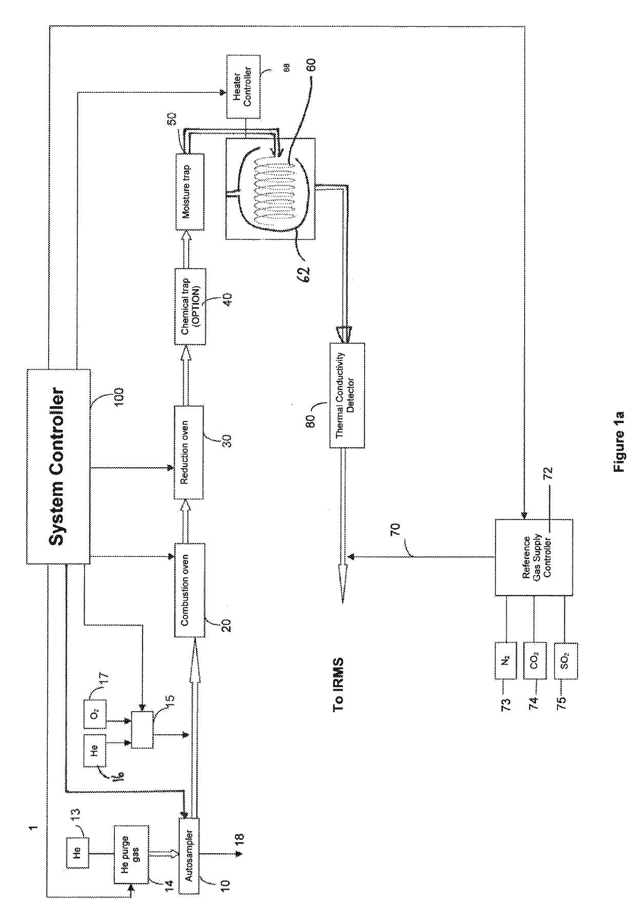
[0065]Referring first to FIG. 3a, a highly schematic arrangement of a sample preparation section of an EA-IRMS in accordance with an embodiment of the present invention is shown. Those components common to FIGS. 1a and 3a are labelled with like reference numerals.

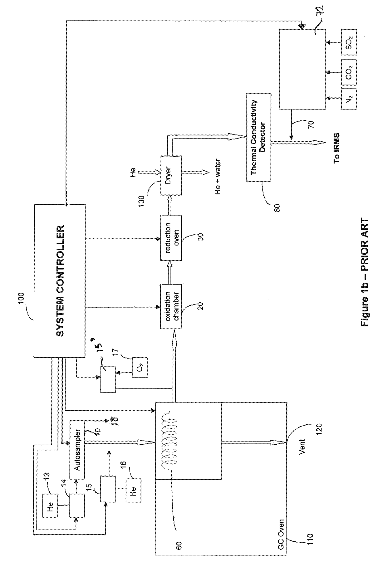
[0066]The sample preparation and combustion / reduction proceeds, in the embodiment of FIG. 3a, in the same manner as was described in the Background section above, in respect of FIG. 1a. To avoid unnecessary repetition, this part of the process will only be summarised here.

[0067]A sample (not shown in FIG. 3a) is weighed and placed in a combustible capsule that is sealed and placed into an autosampler carousel 10 positioned above a combustion furnace 20. The autosampler carousel 10 injects the sealed sample capsule into the combustion furnace 20 under the control of a system controller 200. As before, Helium may be supplied to the autosampler 10 as a purge gas, and combustion in the combustion furnace 20 may be carried out i...


PUM

PropertyMeasurementUnit
fixed temperatureaaaaaaaaaa

Abstract

A sample preparation apparatus for an elemental analysis system comprising a sample combustion and / or reduction and / or pyrolysis arrangement for receiving a sample of material to be analyzed, and producing therefrom a sample gas flow containing atoms, molecules and / or compounds; a gas chromatography (GC) column into which the sample gas flow is directed; a heater for heating at least a part of the GC column; and a controller for controlling the heater. The controller is configured to control the heater so as to increase the temperature of at least the part of the GC column while the sample gas flow in the GC column elutes.

Description

FIELD OF THE INVENTION[0001]This invention relates to an improved sample preparation apparatus for an elemental analysis system such as an elemental analysis isotope ratio mass spectrometer (EA-IRMS). The invention is particularly but not exclusively suitable for simultaneous δ13C, δ15N and δ34S measurements and % C, % N and % S determinations in such a spectrometer.BACKGROUND TO THE INVENTION[0002]Isotope Ratio Mass Spectrometry (IRMS) is a technique that finds application across many fields including geosciences, archaeology, medicine, geology, biology, food authenticity and forensic science. Accurate and precise measurement of variations in the abundances of isotopic ratios of light elements in a sample such as 13C / 12C (δ13C), 15N / 14N (δ15N), 18O / 16O (δ18O), D / H, and 34S / 32S (δ34S), relative to an isotopic standard, can provide information on the geographical, chemical and biological origins of substances, allowing differentiation between samples that are otherwise chemically ide...

Claims


Application Information

Patent Timeline
Patent Type & Authority Patents(United States)
IPC IPC(8): H01J49/04G01N30/12G01N30/72H01J49/42G01N30/30B01D59/44G01N31/12
CPCH01J49/0468G01N30/12G01N30/30G01N30/7206H01J49/426H01J49/0422G01N2030/3076B01D59/44G01N31/12G01N2030/125G01N30/06
Inventor BRODIE, CHRISTOPHERKRACHT, OLIVERHARTWIG, ALEXANDERKRUMMEN, MICHAELSCHWIETERS, JOHANNES
Owner THERMO FISHER SCI BREMEN
Why Eureka
Try Eureka