
Crystallization column and crystallization method

a crystallization column and crystallization technology, applied in the field of chemical engineering, can solve the problems of high volume and energy consumption of the crystallization column still exiting, low cooling production efficiency, and high volume and energy consumption of the crystallization column, and achieves low cost, high crystallization efficiency, and simple structure

Active Publication Date: 2019-08-20
CHINA PETROCHEMICAL CORP +1
View PDF11 Cites 0 Cited by
  • Summary
  • Abstract
  • Description
  • Claims
  • Application Information

AI Technical Summary

Benefits of technology

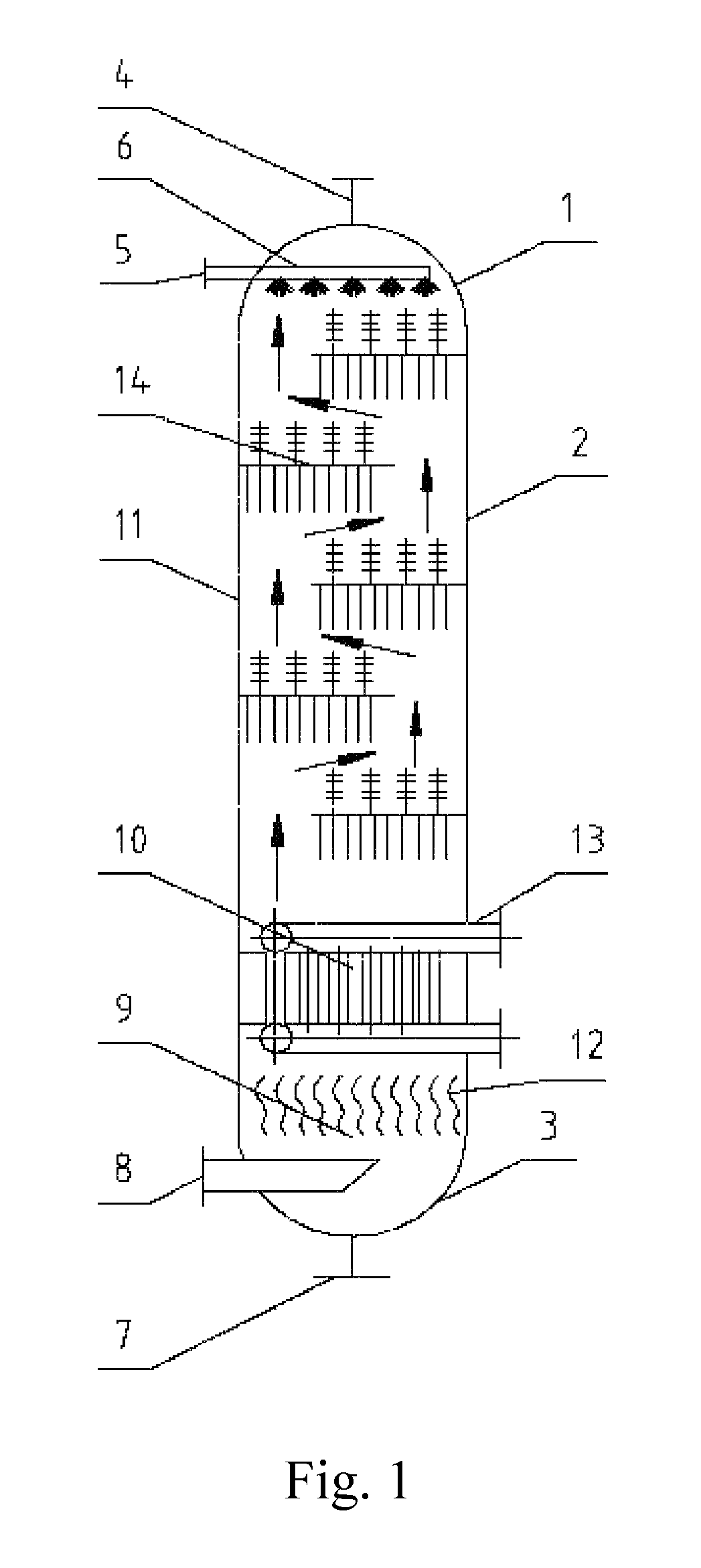
[0005]Aiming at the above-mentioned defects or deficiencies in the prior art, the invention provides a crystallization column and a crystallization method thereof. The crystallization column is simple in structure, low in cost, high in crystallization efficiency and easy in dropping of crystal substances. In order to fulfill the above-mentioned aim, a crystallization column is provided in accordance with one aspect of the invention, which comprises an upper head with a gas outlet, a tower body and a lower head with a gas inlet and a material outlet, wherein the tower body comprises a crystallization section; a tray is arranged in the crystallization section and comprises a tray plate extending from the inner wall of the tower body and a plurality of lower crystallization members which are arranged on the lower surface of the tray plate at intervals with each other.
[0016]Compared with the prior art, the crystallization column of the invention at least has the following advantages:
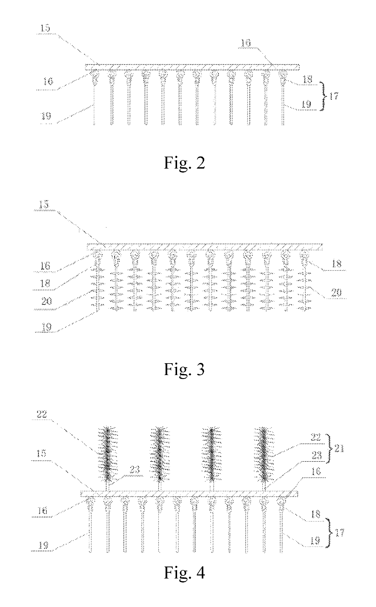
[0017]1) In the crystallization column of the invention, the tray and a plurality of lower crystallization members which are hung are arranged in the crystallization section; when flowing through the lower crystallization member, reactant gas is easily in crystallized attachment to the surface of the lower crystallization member. The gas phase flows through the lower crystallization member, there is a difference in flowing around the lower crystallization member; crystallized attachment is in the non-uniform state, and the oscillation of the lower crystallization member is easy to cause under the swaying of gas-phase flowing and the offset of center of gravity, hence, once producing collision with the adjacent lower crystallization members, the crystal substances will be crushed and stripped to drop the next layer of tray or the bottom of the tower body, thereby achieving easiness in the crystallization and stripping of the crystallization column of the invention;
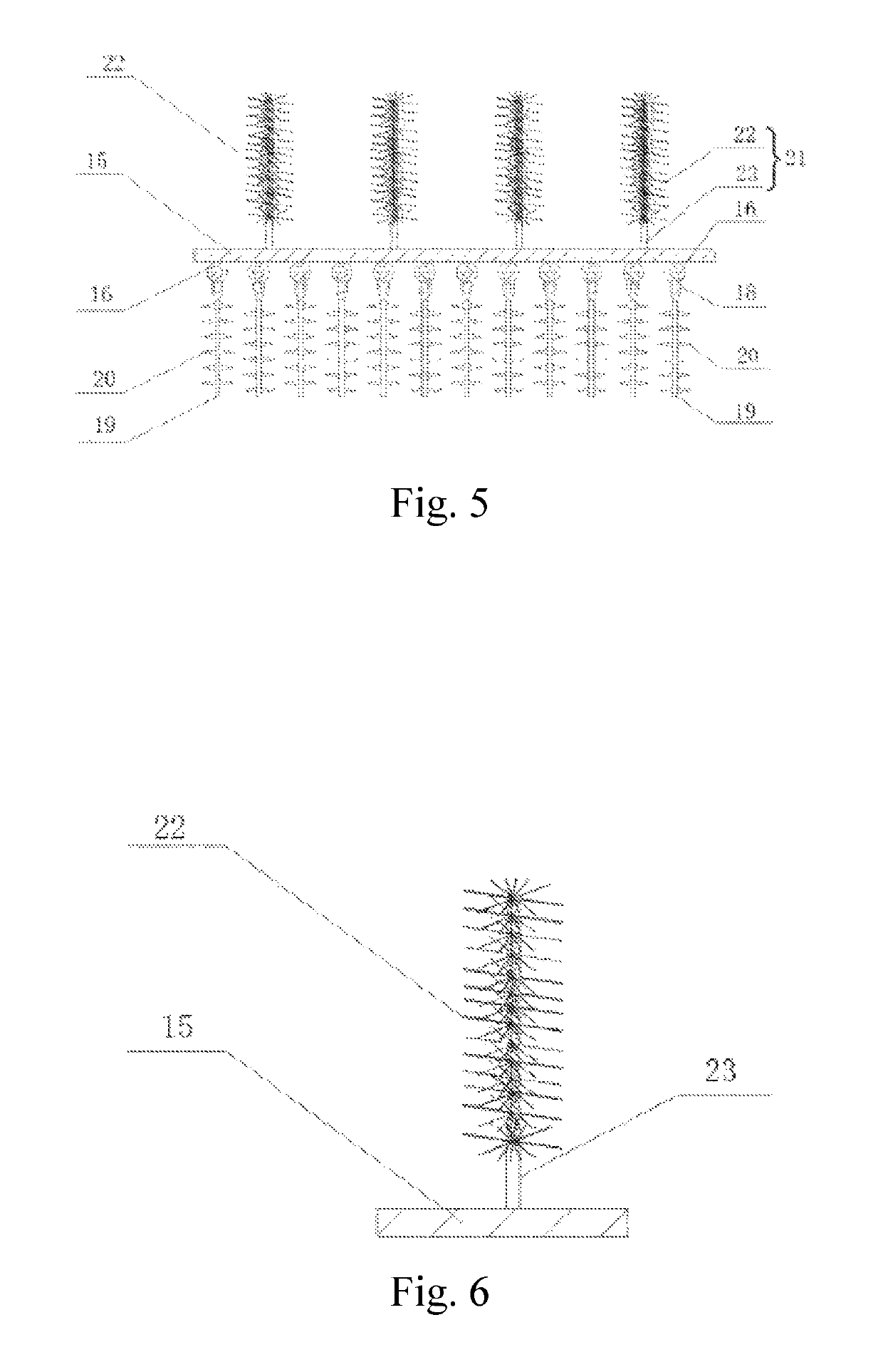
[0018]2) In the crystallization column of the invention, the attachment areas of the crystal substances are greatly increased by arranged the torsion wire brushed type upper crystallization member; when the crystal substances on the previous layer of tray drop, the wire space of the upper crystallization member still exits, making the dropped crystal substances in the fluffy state, reactant gas still can pass through the space, and crystallized attachment can be sequentially formed in the such process; and the surfaces of the dropped crystal substances can also be used as the crystallized attachment surfaces, thereby greatly increasing the areas of the crystallized attachment surfaces. When the crystal substances are filled in the gap of the torsion wire brushed type upper crystallization member, operation is switched, and water is injected into the top of the crystallization column filled with the crystal substances, and as the crystal substances are in the fluffy state between the gaps of the torsion wire brushed type crystallization column, which is extremely easy drop to the tray plate under the impulsion of a water injection distributor;
[0019]3) The crystallization column of the invention is large in surface areas of the attached crystal substances, easy in dropping and accumulation of crystal substances on the tray, small in water injection amount and high in concentration of acidic water, can effectively reduce the energy consumption of the steam stripping of acidic water, is suitable for the ammonium hydrosulfide crystallization process in the acidic water treatment process of the refinery plant, and is particularly suitable for the separation process of hydrogen sulfide in acid gas containing carbon dioxide.

Problems solved by technology

At present, cooling crystallization equipment mainly applies dividing wall cooling crystallization equipment and vacuum cooling crystallization equipment, wherein most of the dividing wall cooling crystallization equipment is provided with jacket cooling crystallization tanks, which are high in water consumption, easy in scaling on the heat exchange surface and low in cooling production efficiency; and the vacuum cooling crystallization equipment is only used in minority of enterprises, and generally, owing to sprayed vacuumizing under steam, the energy consumption of steam is higher.
In order to overcome the defects and deficiencies of the dividing wall cooling crystallization equipment and the vacuum crystallization equipment, the air-cooled crystallization column has been applied in the cooling crystallization of chemical industry production, however, the problems of high volume and energy consumption of the crystallization column still exit.
In addition, the existing crystallization column has the problems of difficult dropping of crystal substances, high energy consumption and low concentration of acidic water formed, resulting in resource wastes.
For example, the conventional crystallization column structure formed by multiple layers of perforated plates is complex and high in costs, crystal substances are easy to enrich and can be firmly bound to the crystallization plate without dropping, and are required to be dropped by means of the periodic vibration of additional vibration equipment on the crystallization column, resulting in high energy consumption.
In addition, the blockage of crystal substances on perforated holes is also required to be prevented, and even shutdown is also required at variable intervals to maintain or assist the dropping of crystal substances, achieving low efficiency of crystallization column.
In addition, when the crystal substances are difficult to drop, for high water volume for washing crystal substances and low concentration of acidic water formed, it is the problem to be solved during the design of the crystallization column.

Method used


Image

  • Crystallization column and crystallization method
  • Crystallization column and crystallization method
  • Crystallization column and crystallization method

Examples


embodiment 1

[0043]The crystallization column as shown in FIG. 1 takes the acid gas as the raw material for processing. In the acid gas, CO2 has a volume fraction of 94%, H2S has a volume fraction of 5%, and hydrocarbon has a volume fraction of 1%. The acid gas is first cooled to 20° C. by the cooler, and then uniformly mixed with the ammonia gas. The feed molar ratio of the acid gas and the ammonia gas is 2:3. The mixed material flow enters the crystallization column to obtain the gas phase material flow and the ammonium hydrogen sulphide crystal. The ammonium hydrogen sulphide crystal is deposited within the crystallization column. The result of analysis of the materials is shown in table 1.


PUM

PropertyMeasurementUnit
diameteraaaaaaaaaa
diameteraaaaaaaaaa
diameteraaaaaaaaaa

Abstract

A crystallization column and a crystallization method. The crystallization column comprises an upper head (1), a tower body (2) and a lower head (3), wherein a crystallization section (11) is provided with a tray (14); and the tray (14) comprises a tray plate (15) and a plurality of lower crystallization members (17). The top end of the lower crystallization member (17) can form a movable connection with the tray plate (15), so that the two adjacent lower crystallizing members (17) are capable of oscillating collisions. The tray (14) may also comprise a plurality of upper crystallization members (21) extending upwardly from the upper surface of the tray plate (15).

Description

FIELD OF THE INVENTION[0001]The invention belongs to the field of chemical engineering, and relates to crystallization equipment for a gas-phase reaction, in particular to a crystallization column for treating two gas reactions to produce a solid phase and a crystallization method thereof.BACKGROUND OF THE INVENTION[0002]Crystallization is the process in which solid matters are precipitated from steam, solution or melts in the crystal state. The traditional industrial crystallization research field, generally, can be divided into four categories, i.e., solution crystallization, melt crystallization, precipitate crystallization and sublimation crystallization.[0003]Crystallization equipment is important unit chemical equipment. At present, cooling crystallization equipment mainly applies dividing wall cooling crystallization equipment and vacuum cooling crystallization equipment, wherein most of the dividing wall cooling crystallization equipment is provided with jacket cooling cryst...

Claims


Application Information

Patent Timeline
Patent Type & Authority Patents(United States)
IPC IPC(8): B01D7/02B01D53/52B01D53/00C01C1/20B01D9/00
CPCB01D7/02B01D9/0013B01D9/0045B01D53/002C01C1/20B01D53/52B01D2251/2062B01D9/005B01D2009/0086
Inventor PENG, DEQIANGQI, HUIMINWANG, LUYAOCHEN, XINMENG, FANFEIWANG, YANLIU, JIE
Owner CHINA PETROCHEMICAL CORP
Learn More