
Method and plant for CO2 capture

a technology of co2 and absorbents, applied in the field of co2 capture from gas, can solve the problems of large waste, potential carcinogenicity, and less energy efficient water solutions of carbonates as cosub>2 /sub>absorbents, and achieve the effects of less energy consumption, less energy consumption, and energy saving

Active Publication Date: 2019-08-27
CAPSOL EOP AS
View PDF13 Cites 0 Cited by
  • Summary
  • Abstract
  • Description
  • Claims
  • Application Information

AI Technical Summary

Benefits of technology

The present invention relates to a method for capturing CO2 from a CO2-containing exhaust gas. The method involves compressing and cooling the exhaust gas before it is introduced into an absorber. The exhaust gas is then counter-currently flowed with an aqueous CO2 absorbent solution in the absorber, where the absorbent absorbs CO2. The rich absorbent is collected at the bottom of the absorber and withdrawn. The absorbent is then regenerated in a regenerator by stripping it with steam to release CO2. The regenerated absorbent is returned to the absorber. The method is efficient in recycling heat energy and conserves energy. The use of carbonates as CO2 absorbents is preferred over amines due to their environmental friendliness and potential carcinogenicity. The method also involves flashing the lean absorbent to generate steam and using it as stripping steam in the regenerator, which further improves energy efficiency.

Problems solved by technology

Aqueous solutions of carbonates as CO2 absorbents are less energy efficient, and needs higher temperature steam for regeneration of the absorbent, than amine based aqueous CO2 absorbents.
Amines or by-products caused by degradation of amines during the CO2 capture process, are known to be potentially carcinogenic, potentially poisonous, and to create large amounts of waste.

Method used


Image

  • Method and plant for CO<sub>2 </sub>capture
  • Method and plant for CO<sub>2 </sub>capture

Examples


example

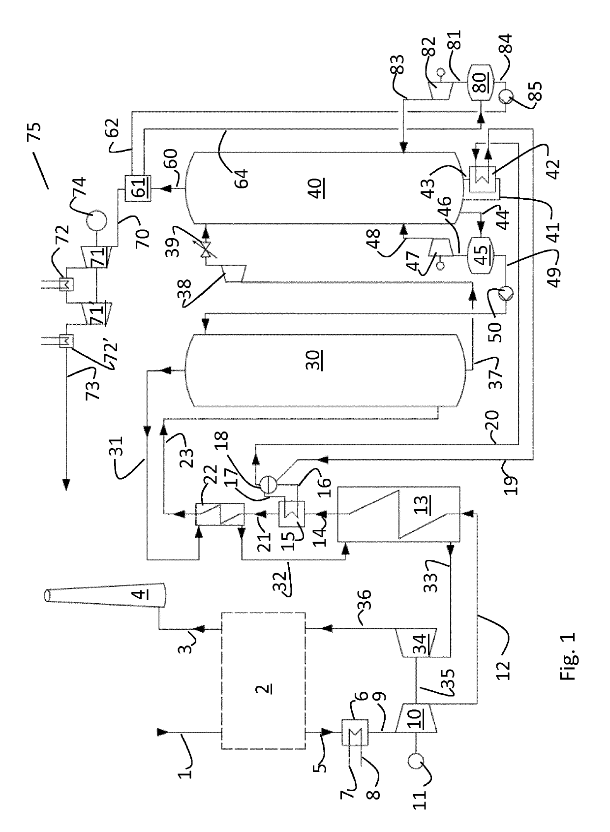
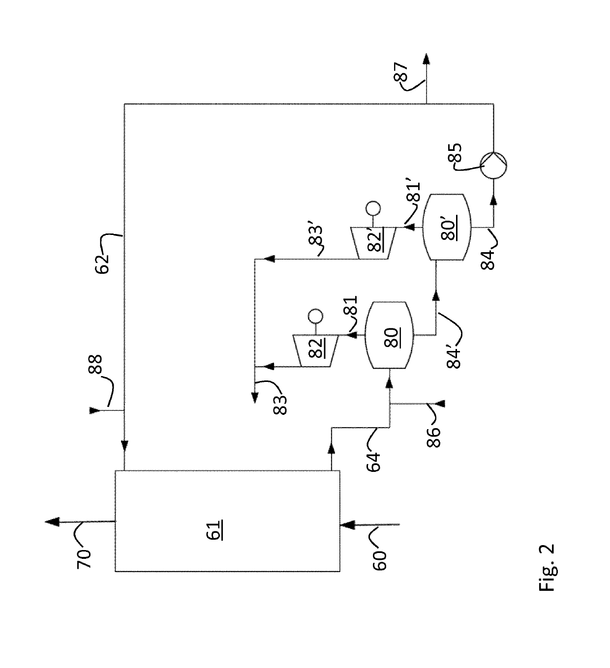
[0043]Calculations have been made for a plant as described above, with reference to FIG. 1 and the embodiment of the flashing or the cooling water for the recuperator cooler 61 as described with reference to FIG. 2.

[0044]The calculations are made based on an incoming exhaust gas from a coal fired power plant at generation / transformation of 565 MW thermal, which based on an average power efficiency of about 45% give 254 MWe. 235.8 kg / s exhaust gas, including 53.4 kg / s CO2, i.e. 22.7% by weight CO2 of the total exhaust gas, is produced. The temperature is 90° C. The calculations are based on capture of 48 kg / s CO2, giving an efficiency of the capturing of about 90%, which is close to, or higher, than the normally specified efficiency of CO2 capture in such CO2 capture facilities.

[0045]In the calculated example, the exhaust gas is cooled from 90° C., to 25° C. in the exhaust gas cooler 6, resulting in condensation of water which reduces the exhaust gas mass flow to 225 kg / s, subsequent...


PUM

PropertyMeasurementUnit
pressureaaaaaaaaaa
pressureaaaaaaaaaa
pressureaaaaaaaaaa

Abstract

A method and plant for capturing CO2 from a CO2 containing exhaust gas (1), where the exhaust gas is compressed (10) and thereafter cooled (13, 15, 22) before the exhaust gas is introduced into an absorber (30), where the exhaust gas is brought in counter-current flow with an aqueous CO2 absorbent solution (49), to give a lean exhaust gas (31) that is withdrawn from the absorber (30), reheated 22, 13) against incoming compressed exhaust gas, and thereafter expanded (34) and released into the atmosphere (4), where the aqueous CO2 absorbent solution is an aqueous potassium carbonate solution, and that the steam and CO2 withdrawn from the regenerator (40) is cooled in a direct contact cooler (61) by counter-current flow of cooling water (62), to generate a gaseous flow (70) of cooled CO2 and steam that is withdrawn for compression and drying of the CO2, and a liquid flow (64) of cooling water and condensed steam that is withdrawn and flashed (80), to give a cooled liquid phase (84) that is recycled as cooling water for the direct contact cooler (61) for the withdrawn CO2 and steam, and a gaseous phase (81) that is compressed (82) and thus heated, and introduced into the regenerator (40) as stripping steam (83).

Description

TECHNICAL FIELD[0001]The present invention relates to CO2 capture from a gas, such as, but not limited to, an exhaust gas from combustion of carbonaceous fuel or any industrial gas having a high concentration of CO2. The present invention more specifically relates to improvements in CO2 capture at elevated pressures, and to improvements reducing the heat loss in connection with CO2 capture.BACKGROUND ART[0002]The increase in CO2 concentration in the atmosphere and the greenhouse effect caused by CO2 is of great concern, and has caused a change towards renewable energy resources and an environmental pressure towards stopping or at least reducing the use of fossil fuels. However, due to both the low cost of carbonaceous fuels and the steady growing demand for energy, and especially energy in the form of electricity for further development in the less industrial parts of the world, carbonaceous fuels will be important as energy sources for decades to come. CO2 capture and storage / depos...

Claims


Application Information

Patent Timeline
Patent Type & Authority Patents(United States)
IPC IPC(8): B01D53/96B01D53/62B01D53/18B01D53/78F23J15/04B01D53/34
CPCB01D3/00B01D3/007B01D3/008B01D3/06B01D3/065B01D3/38B01D53/00B01D53/002B01D53/14B01D53/1425B01D53/1475B01D53/18B01D53/34B01D53/343B01D53/40B01D53/62B01D53/77B01D53/78B01D53/96B01D2251/306B01D2251/606B01D2257/504B01D2258/0283B01D2259/65B01D2259/652F23J15/04Y02A50/20Y02C20/40Y02E20/32
Inventor HAMRIN, STELLAN
Owner CAPSOL EOP AS
Learn More