Method and system for scribing brittle material followed by chemical etching

a technology of chemical etching and brittle materials, applied in the direction of manufacturing tools, welding/soldering/cutting articles, layered products, etc., can solve the problems of increased production cost, increased cleaning and polishing steps, and poor quality edges, so as to avoid damage to the metal layer

Active Publication Date: 2019-08-27
ROFIN SINAR TECH
View PDF95 Cites 2 Cited by
  • Summary
  • Abstract
  • Description
  • Claims
  • Application Information

AI Technical Summary

Benefits of technology

[0012]A burst of ultrafast laser pulses is focused such that a beam waist is formed external to the material being processed, such that a primary focus does not form within the material, while a sufficient energy density is formed within an extended region within the material to support the formation of a continuous filament, without causing optical breakdown within the material. Filaments formed according to this method may exhibit lengths exceeding up to 10 mm with a 1:1 correspondence in the length of the modified zone (in that the filament is the agent of modification, so the modified zone tracks 1:1 with the extent of the filament) and a taper-free profile when viewed with the long axis in cross-section. In some embodiments, an uncorrected or aberrated optical focusing element is employed to produce an external beam waist while producing distributed focusing (elongated focus) of the incident beam within the material. Various systems are described that facilitate the formation of filament arrays within transparent substrates for cleaving / singulation and / or marking. Optical monitoring of the filaments may be employed to provide feedback to facilitate active control of the process.
[0049]Very fine closed form structures can be scribed via filamentation in the transparent substrate very quickly, the modified zone can be etched via dry or wet chemical etching to release the closed form.

Problems solved by technology

This process creates poor quality edges, microcracks, wide kerf width, and substantial debris that are major disadvantages in the lifetime, efficiency, quality, and reliability of the product, while also incurring additional cleaning and polishing steps.
The cost of de-ionized water to run the diamond scribers are more than the cost of ownership of the scriber and the technique is not environmentally friendly since water becomes contaminated and needs refining, which further adds to the production cost.
Unfortunately, known laser processing methods have disadvantages, particularly in transparent materials, such as slow processing speed, generation of cracks, contamination by ablation debris, and moderated sized kerf width.
Furthermore, thermal transport during the laser interaction can lead to large regions of collateral thermal damage (i.e. heat affected zone).
However, the aforementioned disadvantages cannot be eliminated due to the aggressive interactions inherent in this physical ablation process.
This is amply demonstrated by the failings of UV processing in certain LED applications where damage has driven the industry to focus on traditional scribe and break followed by etching to remove the damaged zones left over from the ablative scribe or the diamond scribe tool, depending upon the particular work-around technology employed.
However, in general, the machining of transparent materials with pulses even as short as tens to hundreds of femtoseconds is also associated with the formation of rough surfaces, slow throughput and micro-cracks in the vicinity of laser-formed kerf, hole or trench that is especially problematic for brittle materials like alumina (Al2O3), glasses, doped dielectrics and optical crystals.
Further, ablation debris will contaminate the nearby sample and surrounding devices and surfaces.
This approach suffers from the need to make multiple passes and therefore results in low processing throughput.
Although laser processing has been successful in overcoming many of the limitations associated with diamond cutting, as mentioned above, new material compositions have rendered the wafers and panels incapable of being laser scribed.
Furthermore, the size of the devices and dice on the wafers are getting smaller and closer to each other that limit the utility of both diamond and conventional laser-based scribing.
For example, 30 μm is a feasible scribing width, while 15 μm is challenging for these conventional methods.
Moreover, as diamond scribing uses mechanical force to scribe the substrate, thin samples are very difficult to scribe.
Due to the use of increasingly exotic and complex material stacks in the fabrication of wafer-based devices, the laser scribing techniques previously applied will simply no longer work due to the opacity of the stack.

Method used


Image

  • Method and system for scribing brittle material followed by chemical etching
  • Method and system for scribing brittle material followed by chemical etching
  • Method and system for scribing brittle material followed by chemical etching

Examples


Embodiment Construction

[0079]Embodiments of the disclosure will now be described by way of example only.

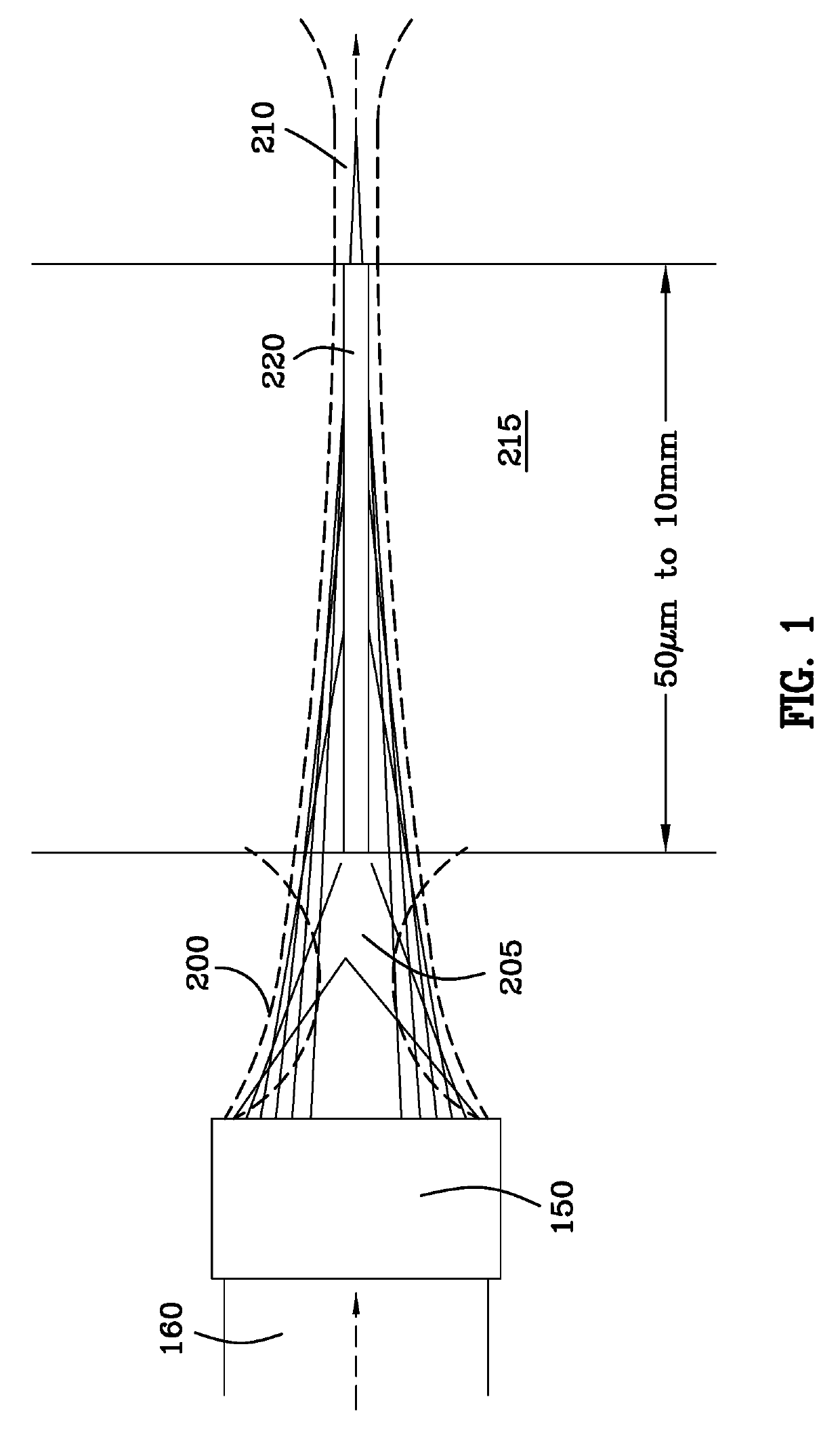
[0080]FIG. 1 illustrates optical configurations for the formation of filaments in which long homogeneous filaments 220 are formed by focusing the beam energy such that it is “dumped” into a focus above and / or below the transparent target material (forming an optical reservoir 220) in order to modulate the amount of energy passed into the desired filament zone. Incoming laser beam 160 passes through a distributed focus assembly 150 which creates foci above or below 210 the target substrate 215.

[0081]The propagation of ultrafast laser pulses in transparent optical media is complicated by the strong reshaping of the spatial and temporal profile of the laser pulse through a combined action of linear and nonlinear effects such as group-velocity dispersion (GVD), linear diffraction, self-phase modulation (SPM), self-focusing, multiphoton / tunnel ionization (MPI / TI) of electrons from the valence band to the con...


PUM

PropertyMeasurementUnit
lengthaaaaaaaaaa
widthaaaaaaaaaa
speedsaaaaaaaaaa

Abstract

Very fine closed form structures can be scribed via filamentation in the transparent substrate very quickly, the modified zone can be etched via dry or wet chemical etching to release the closed form. A metal layer engages the transparent substrate and is covered with photoresist. A portion of the photoresist and a portion of the metal are removed simultaneously with the creation of a filament through the transparent substrate. The photoresist protects the portion of the metal layer that is not removed. The desired closed form can be released by weakening the cut region using dry or wet chemical etching to remove the desired part.

Description

[0001]This patent application claims the benefit and priority of U.S. provisional patent application Ser. No. 62 / 103,031 filed Jan. 13, 2015. U.S. provisional patent application Ser. No. 62 / 103,031 filed Jan. 13, 2015 is incorporated herein by reference hereto in its entirety.[0002]U.S. patent application Ser. No. 13 / 640,140, filed Jan. 31, 2013, U.S. patent application Ser. No. 14 / 336,912, filed Jul. 21, 2014, and U.S. patent application Ser. No. 14 / 336,819, filed Jul. 21, 2014 are hereby incorporated herein by reference hereto as if fully written herein.BACKGROUND OF THE INVENTION[0003]The present disclosure is related to systems and methods for the laser processing of materials. More particularly, the present disclosure is related to systems and methods for the singulation and / or cleaving of wafers, substrates, and plates containing passive or active electronic or electrical devices created upon said materials.[0004]In current manufacturing, the singulation, dicing, scribing, cle...

Claims


Application Information

Patent Timeline
Patent Type & Authority Patents(United States)
IPC IPC(8): B32B3/00B23K26/402B23K26/362B23K26/0622B23K26/364B23K26/361B23K103/00
CPCB23K26/364B23K26/0624B23K26/361B23K2103/50B23K26/0622B23K2103/56B23K2103/54B23K26/402B23K26/362
Inventor HOSSEINI, S. ABBAS
Owner ROFIN SINAR TECH
Why Eureka
Try Eureka