Fuel cell separator

a fuel cell and separator technology, applied in the direction of fuel cells, electrical equipment, electrochemical generators, etc., can solve the problems of fuel cell output decline, cracking and breakage, and performance decline, and achieves good heat dissipation performance, and good heat dissipation

Active Publication Date: 2019-08-27
NISSHINBO CHEM
View PDF20 Cites 0 Cited by
  • Summary
  • Abstract
  • Description
  • Claims
  • Application Information

AI Technical Summary

Benefits of technology

[0024]The fuel cell separator of the invention has an excellent resistance to wet heat, and moreover maintains such wet heat resistance for a long time. That is, because the separator undergoes little change in contact resistance even after prolonged exposure to a wet heat environment, fuel cells equipped with the fuel cell separator of the invention are able to maintain a stable power generating efficiency over a long period of time.EMBODIMENT FOR CARRYING OUT THE INVENTION
[0025]The fuel cell separator of the invention is obtained by molding a composition containing graphite powder and an epoxy resin (which composition is referred to below as the “fuel cell separator composition”).[Fuel Cell Separator Composition]
[0026]The graphite powder included in the fuel cell separator composition may be a natural graphite or synthetic graphite. Vein graphite or a synthetic graphite powder obtained by spheroidizing vein graphite is especially preferred. The graphite powder has a mean particle size d50 of preferably from 20 to 100 μm, and more preferably from 30 to 80 μm. At a mean particle size d50 below 20 μm, a thermosetting resin readily covers the surface of the graphite material and the surface area of contact between particles becomes smaller, as a result of which the electrical conductivity of the separator itself may worsen. At a mean particle size greater than 100 μm, the surface area of contact between the graphite particles and the thermosetting resin becomes smaller and so a sufficient mechanical strength may not be attainable. The mean particle size d50 in this invention refers to the median diameter in particle size analysis by the laser diffraction method.
[0027]For a fuel cell separator to exhibit a sufficient strength even when it is thin-walled, a porous synthetic graphite material containing not more than 1 wt % of graphite particles up to 1 μm in size and containing not more than 1 wt % of graphite particles at least 300 μm in size is more preferred. A synthetic graphite material in which the content of particles up to 3 μm in size is not more than 1 wt % and the content of particles at least 250 μm in size is not more than 1 wt % is best.
[0028]The specific surface area of the graphite powder is preferably from 1 to 5 m2 / g. At a specific surface area for the graphite powder of less than 1 m2 / g, compatibility between the graphite material and the resin worsens and sufficient strength may not be obtained. On the other hand, at a specific surface area for the graphite powder of more than 5 m2 / g, the graphite material ends up absorbing the resin, thus worsening the flowability of the molding material. As a result, the thickness accuracy may worsen and the contact resistance may increase. Moreover, the graphite material ends up absorbing both water that forms in association with the cell reactions by the fuel cell and cooling water, giving rise to warping of the separator, as a result of which the contact resistance may increase.
[0029]The epoxy resin within the composition for a fuel cell separator includes a base resin, a curing agent and a curing accelerator.

Problems solved by technology

Although the separator of Patent Document 1 has a low water uptake (saturation water uptake) when immersed for ten days in hot water at 80° C. of 0.4 to 0.6%, because this remains inadequate for sustained power generation by a fuel cell operating at generally from 60 to 80° C., drawbacks include decreased performance due to swelling of the separator from water absorption, and also cracking and breakage on account of non-uniform extension.
Also, because hexamine is used in the phenolic resin curing agent, the ammonium ions that form as a result of hexamine decomposition dissolve out during operation of the fuel cell, leading to a decline in fuel cell output and reduced stability in sustained power generation.
However, because both of these separators use an ortho-cresol novolak-type epoxy resin having a high water uptake as the main ingredient of the binder resin, decreased performance and failure arise due to water uptake by the separator during sustained power generation by the fuel cell.
On the other hand, because the crosslink density is low, they have a poor heat resistance, making it necessary to select a resin having a high molecular weight.
However, high-molecular-weight resins have a high melt viscosity, and so the flowability of the composition during molding is poor, resulting in a large variation in thickness and a high initial contact resistance.
Because high-para novolak-type phenolic resins have a low crystallinity, the melt viscosity is high and the flowability of the composition during molding is poor, resulting in a large thickness variation and a high initial contact resistance.
In Patent Document 5, slow-reacting 2,3-dihydro-1H-pyrrolo(1,2-a)benzimidazole is used as the curing accelerator, and so formation takes a full 2 minutes, which is a problem in terms of productivity.

Method used


Image

  • Fuel cell separator
  • Fuel cell separator
  • Fuel cell separator

Examples


examples

[0059]Examples of the invention and Comparative Examples are given below by way of illustration and not by way of limitation.

[0060]Measurements and evaluations of various physical values and characteristics were carried out by the following methods.

[ICI Viscosity]

[0061]The ICI viscosity was measured at a plate temperature of 150° C. using an ICI cone and plate viscometer from Codex Corp.

[Mean Particle Size d50]

[0062]The mean particle size was measured using a particle size analyzer (Microtrac MT3000, from Nikkiso Co., Ltd.).

[Thickness Variation]

[0063]The separator thickness was measured at 20 points on each separator with a micrometer (Digimatic PMU150-25DM, from Mitutoyo Corporation), and the average thickness was determined. The variation in thickness was calculated from the following formula.

Thickness variation (%)=[(maximum thickness−minimum thickness) / average thickness]×100

[Glass Transition Point]

[0064]Using a thermal analyzer (TMA 6100, from Seiko Instruments Inc.), measuremen...

working examples 1 to 4

, Comparative Examples 1 to 5

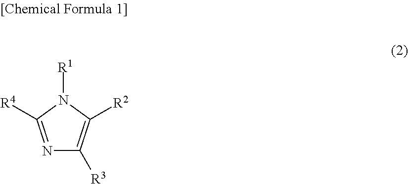
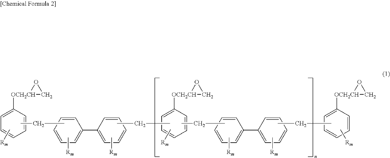
[0073]In each Example, a fuel cell separator composition was prepared by charging the following ingredients in the amounts shown in Table 1 into a Henschel mixer and mixing them together for 3 minutes at 500 rpm: synthetic graphite powder as the graphite powder, biphenyl novolak-type epoxy resin as the base resin of the epoxy resin, novolak-type phenolic resin as the curing agent of the epoxy resin, 2-phenylimidazole as the curing accelerator, and carnauba wax as the internal mold release agent.

[0074]The resulting composition was poured into a 200×200×2 mm mold for fuel cell separator production and compression-molded at a mold temperature of 185° C., a molding pressure of 30 MPa and a molding time of 30 seconds to give a fuel cell separator.


PUM

PropertyMeasurementUnit
ICI viscosityaaaaaaaaaa
dispersityaaaaaaaaaa
mean particle size d50aaaaaaaaaa

Abstract

Provided is a fuel cell separator obtained by molding a composition that contains an epoxy resin and a graphite powder, wherein: the epoxy resin contains a main resin, a curing agent, and a curing accelerator; the main resin contains a biphenyl novolak-type epoxy resin having an ICI viscosity of 0.03-0.12 Pa·s at 150° C.; and the curing agent is a novolak-type phenol resin having a weight-average molecular weight of 420-1,500 and a dispersion degree of 2.0 or less.

Description

TECHNICAL FIELD[0001]This invention relates to a fuel cell separator.BACKGROUND ART[0002]Fuel cell separators, together with carrying out the roles of imparting electrical conductivity to each unit cell and of providing flow channels for the supply of fuel and air (oxygen) to the unit cells, also serve as boundary walls separating the unit cells. Characteristics required of a separator thus include high electrical conductivity, high impermeability to gases, chemical stability, heat resistance and hydrophilicity. Techniques known for increasing these characteristics include the methods disclosed in Patent Documents 1 to 5.[0003]Patent Document 1, the object of which is to provide a method for producing a solid polymer fuel cell separator that can be stably used over a long period of time, discloses a method for producing a solid polymer fuel cell separator which is molded under heat and pressure from a composition containing a phenolic resin solution and graphite powder and the cured...

Claims


Application Information

Patent Timeline
Patent Type & Authority Patents(United States)
IPC IPC(8): H01M8/0226C08G59/62C08G59/50C08L63/04H01M8/0221H01M8/0234H01M8/0239H01M8/0243H01M8/1018
CPCC08K5/3462C08K3/042C08G59/5073C08G59/621C08L63/04H01M8/0221H01M8/0226H01M8/0234H01M8/0239H01M8/0243H01M2008/1095Y02E60/50C08K3/04
Inventor TANNO, FUMIO
Owner NISSHINBO CHEM
Why Eureka
Try Eureka