Bi-metal foil for a beam intensity/position monitor, method for determining mass absorption coefficients

a beam intensity/position monitor and bi-metal foil technology, applied in the direction of optical radiation measurement, instruments, photomechanical equipment, etc., can solve the problems of inability to meet all cross-section requirements through printed tables, unstable electronic structure of atoms, and time-consuming manual switching of foils

Active Publication Date: 2019-12-03
UCHICAGO ARGONNE LLC
View PDF5 Cites 0 Cited by
  • Summary
  • Abstract
  • Description
  • Claims
  • Application Information

AI Technical Summary

Benefits of technology

[0025]Another object of the invention is to provide a beam position monitor substrate that can be used over a wide range of energies. A feature of the invention is that it comprises a bi-metal component of two different metals. An advantage of the invention is that it increases the operating range of a fluorescing metal-foil based beam position monitor by providing characteristics of two metals within a single foil. For example, an invented bi-metal foil operates below 6 keV and above 25 keV. As such, foil handling in and out of a beamline is all but eliminated except for the initial installation of the foil into the beam line.
[0026]Still another object of the present invention is to provide a beam intensity monitor that can be used over a wide range of energies. A feature of the invention is that it comprises a bi-metal substrate made of two different metal foils laminated to each other, with a first metal foil situated downstream of a second metal foil. An advantage of the invention is that due to the specific absorption characteristics of the first and second metals, the bimetal foil can be used as an energy calibration device relative to the absorption edges or each metal. This can be done by monitoring one or more photodiode signals or by monitoring the summation of all photodiode signals without need to determine beam position.
[0027]Yet another object of the invention is to provide a method for measuring the absorption cross sections of a first metal foil. A feature of the invention is the use of a transference technique whereby the approximate cross sections are estimated based on the absorption exhibited by the bi-metal foil, as a function of energy. Then, the estimated cross sections are combined with a standalone first metal foil to determine absolute cross section values. An advantage of the invention is that the method has errors at about the 1 percent level compared to 10-50 percent errors in state of the art protocols.
[0028]Briefly, the invention provides a beam positioning monitor substrate comprising a first metal foil in physical contact with a second metal foil.
[0029]Also provided is a method for determining mass absorption coefficients, the method comprising measuring the absorption of an incident radiation beam by a first metal and a second metal comprising a bi-metal foil as a function of a first energy and a second energy. (The absorption by the bimetal foil requires two measurements at each energy (one with the foil in and one with the foil out, which generates a single absorption value for each energy. As such, the utilization of two energies generates two values.)
[0030]Then, the relative first metal thickness is calculated. Optionally, the thicknesses of both the first and second metals comprising the bimetal foil can be calculated, but only one is needed to conduct the fitting, as discussed immediately below.

Problems solved by technology

However, it is not possible to meet all cross-section requirements by means of printed tables.
The removal of an electron in this way makes the electronic structure of the atom unstable, and electrons in higher orbitals “fall” into the lower orbital to fill the hole left behind.
There are a limited number of ways in which this can happen.
However, many crystallographic structural studies embodying Single-wavelength Anomalous Diffraction (SAD) techniques employ lower energy X rays.
Since these beamlines are operating in-vacuum, manual switching of foils would be very time consuming.
In addition, the foils are quite fragile and can easily break with poor handling or during vacuum pump-down procedures.

Method used


Image

  • Bi-metal foil for a beam intensity/position monitor, method for determining mass absorption coefficients
  • Bi-metal foil for a beam intensity/position monitor, method for determining mass absorption coefficients
  • Bi-metal foil for a beam intensity/position monitor, method for determining mass absorption coefficients

Examples


example

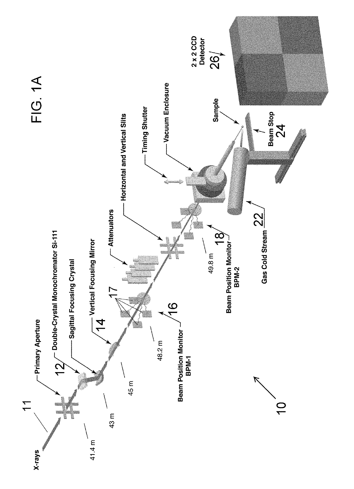
[0079]All measurements were conducted at the Structural Biology Center, bending beamline, 19BM, at the Advanced Photon Source at Argonne Laboratory, Lemont, Ill. Turning to FIG. 1A, the 19BM optics include a Si(111) double-crystal monochromator, a water cooled first crystal with liquid gallium interface, sagittal focusing second crystal web: 25 mm×75 mm×0.58 mm (width×length×thickness), and vertical focusing ultra low expansion glass mirror with Pd, Pt and glass lanes.

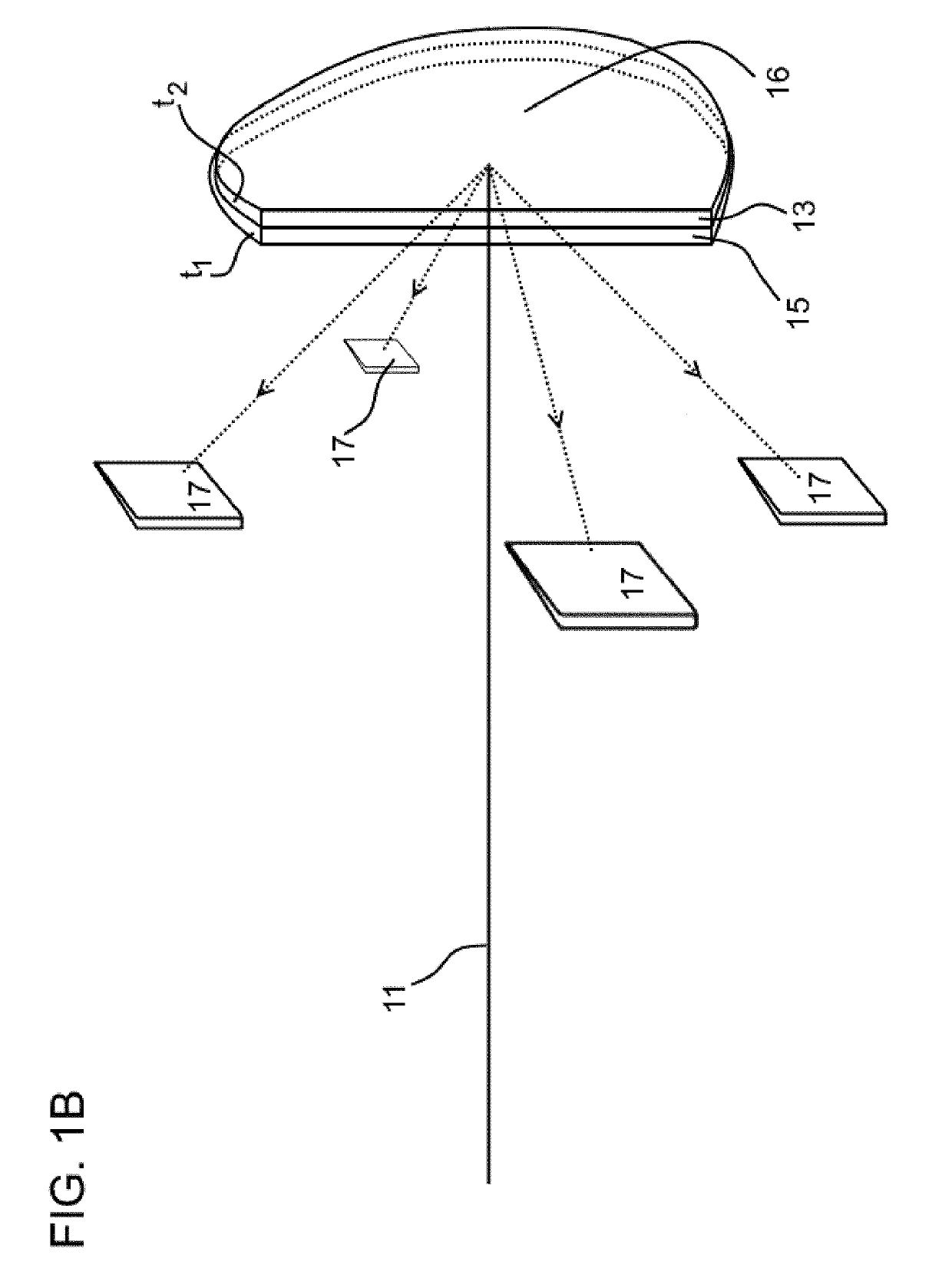
[0080]Downstream of the mirror is the first beam position monitor, BPM-1, which containing the above-described Ti—Ni bi-metal foil. A pneumatic plunger allows the foil holder to move completely out of the beam path. A second beam position monitor, BPM-2, is a fixed (non-movable) foil position containing a nominal 0.5 μm-Cr foil made by Arizona Carbon Foil Co. (2239-T E. Kleindale Rd, Tucson Ariz. 85719, USA). Separation distance between BPM-1 and BPM-2 is 1.6 m. All photodiodes are operated in the unbiased, photovoltai...


PUM

PropertyMeasurementUnit
energyaaaaaaaaaa
thicknessaaaaaaaaaa
energy absorptionaaaaaaaaaa

Abstract

The invention provides a beam intensity / positioning monitor substrate comprising a first metal foil in physical contact with a second metal foil. Also provided is a method for determining mass absorption coefficients, the method comprising measuring the absorption of an incident radiation beam by a first metal and a second metal comprising a bi-metal foil as a function of a first energy and a second energy; calculating the relative first metal thickness; using the relative thickness as a target value for the first metal fitting procedure; repeat the above steps on a free standing first metal foil; using the free standing first metal absorption measurements, bulk first metal density and first (bimetal) fit coefficients to determine first metal foil thickness; using free standing first metal to conduct a high resolution scan from just below its absorption edge to 1 keV or higher in energy; and using the free standing first metal absorption measurements below the absorption edge and experimentally determined thickness to compute mass absorption coefficients below its absorption edge.

Description

CONTRACTUAL ORIGIN OF THE INVENTION[0001]The U.S. Government has rights in this invention pursuant to Contract No. DE-AC02-06CH11357 between the U.S. Department of Energy and UChicago Argonne, LLC, representing Argonne National Laboratory.BACKGROUND OF THE INVENTION1. Field of the Invention[0002]This invention relates to synchrotron beamline diagnostics and measuring mass absorption cross sections. More specifically, this invention relates to beam position monitors for measuring the position of X-ray beams, beam intensity monitors for tracking beam source intensity, energy calibration reference markers and to the determination of mass absorption cross sections using an invented bi-metal foil.2. Background of the Invention[0003]X-rays can be classified as short-wave electromagnetic radiation. They can be produced in parcels of energy called photons. The absorption of X-ray photons by any material depends upon both the structure and elemental composition of the material under study. T...

Claims


Application Information

Patent Timeline
Patent Type & Authority Patents(United States)
IPC IPC(8): H01L21/67G01J1/02G03F7/20H01J37/317H01L31/16H01J37/30H01L31/02H01L31/0336
CPCH01J37/3005G01J1/0204G03F7/2008H01L31/02H01L31/16H01L31/03365H01L21/67253H01J37/3174G01T1/29
Inventor ALKIRE, RANDY
Owner UCHICAGO ARGONNE LLC
Why Eureka
Try Eureka