High efficiency multiplexing

a multi-spectroscopy, high-efficiency technology, applied in the direction of fluorescence/phosphorescence, optical radiation measurement, wave/particle radiation conversion of sensor output, etc., can solve the problems of reducing the duty cycle of micromirror based designs, affecting the efficiency of multi-spectroscopy, and unable to meet the requirements of the application. , to achieve the effect of mechanical robustness and reducing the number of parameters

Active Publication Date: 2020-03-10
10103560 CANADA LTD
View PDF1 Cites 4 Cited by
  • Summary
  • Abstract
  • Description
  • Claims
  • Application Information

AI Technical Summary

Benefits of technology

[0069]This embodiment provides a method to measure the dynamics of recurring phenomena with improved time resolution and improved signal-to noise performance.
[0167]A transmissive region may be constructed by placing transmissive material in the region or more preferably by placing a slot in the region. A reflective region can be constructed by placing a highly reflective material in the region. The reflective material is preferably a metal such as Al, Ag or Au with high reflectivity over a broad spectral range. A dielectric mirror may offer higher reflectivity over a narrower spectral range. Other materials that provide high reflectivity in the spectral region of interest may be used. The angle of incidence may be varied to provide sets of reflective regions directed toward different detectors. In some embodiments, the reflective regions have plane surfaces and in other embodiments, the reflective regions have curved surfaces for the purpose of concentrating EM radiation at a detector. A refractive region may be constructed by placing a material with a refractive index >1 in the region. The refractive material preferably is generally wedge shaped so that the general direction of EM radiation exiting the refractive region is not parallel to the general direction of EM radiation incident on the refractive region. Refractive regions with different exit directions can be constructed by varying the wedge angle. Specifically, two or more sets of regions can be constructed by using two or more distinct wedge angles. The surfaces of refractive regions may be plane or curved for the purpose of concentrating EM radiation at a detector. A diffractive region may be constructed by placing a diffraction grating in the region. The diffraction grating may be transmissive or reflective. As EM radiation with different wavelengths will fall on spatially separated diffractive surfaces in a set with a common grating period, the set of paths leading to a common detector is a line in theta-Z space. It should be noted a diffraction grating may function as several logical regions because incident radiation is directed into several diffraction orders. The relative intensity in each order can be tuned by modifying parameters such as the blaze angle, groove depth or grating material. Diffractive regions with different exit directions may be constructed by varying the grating period. The diffractive surfaces may by plane or curved for the purpose of concentrating EM radiation at a detector. Reflective and refractive regions as envisioned in the present invention lead to spatial modulators that are intrinsically variable in three dimensions compared with prior designs which are essentially two dimensional. Two dimensional spatial modulators are generally easier to fabricate than three dimensional spatial modulators, but three dimensional spatial modulators can provide superior performance. The diffractive regions option has the advantage of allowing multiple output directions combined with ease of fabrication at the cost of reduced efficiency.

Problems solved by technology

These systems faced problems with mask alignment leading to several technical advances, none of which were wholly satisfactory.
These approaches suffer from several problems.
The duty cycle of micromirror based designs is limited by thermal loading.
Furthermore, micromirror designs suffer from diffraction and a non-unity packing fraction.
This design has the advantage of being mechanically robust with no moving parts, but has the disadvantage of requiring a large focal plane array.
In practical terms, this approach is limited to the visible region of the spectrum where silicon based focal plane arrays are inexpensive.
A key drawback common to all of the Hadamard variants noted above is that even if optical losses are neglected, only half of the EM radiation entering the entrance aperture is received by the detector(s), on average.
Fateley does not provide any disclosure about how to use the information from a second detector.
A further limitation of all the Hadamard variants noted above is that the best spectral resolution achievable is limited by the fixed geometry of the mask element size.
The difference is attributed to imperfect separation of the ion flux contributing to the wrong detector channel.

Method used


Image

  • High efficiency multiplexing
  • High efficiency multiplexing
  • High efficiency multiplexing

Examples


Embodiment Construction

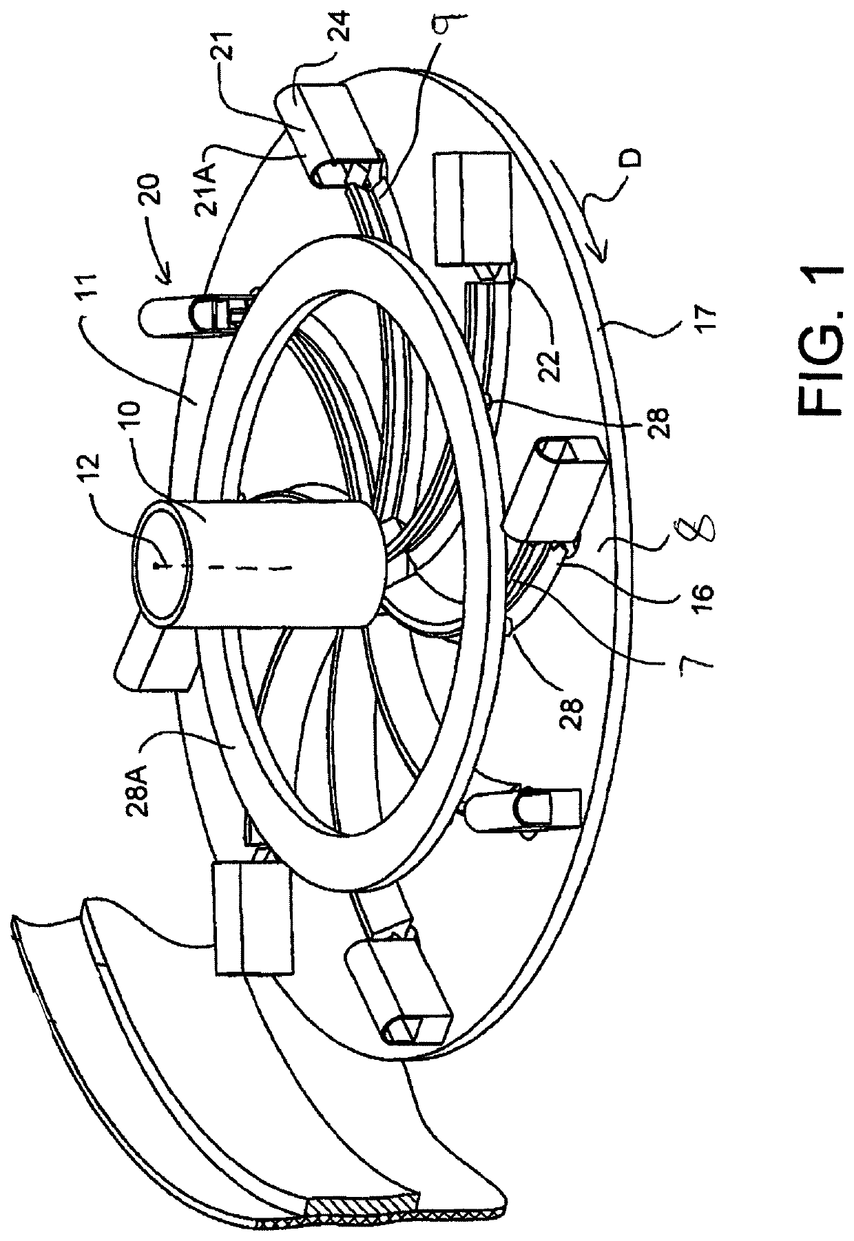
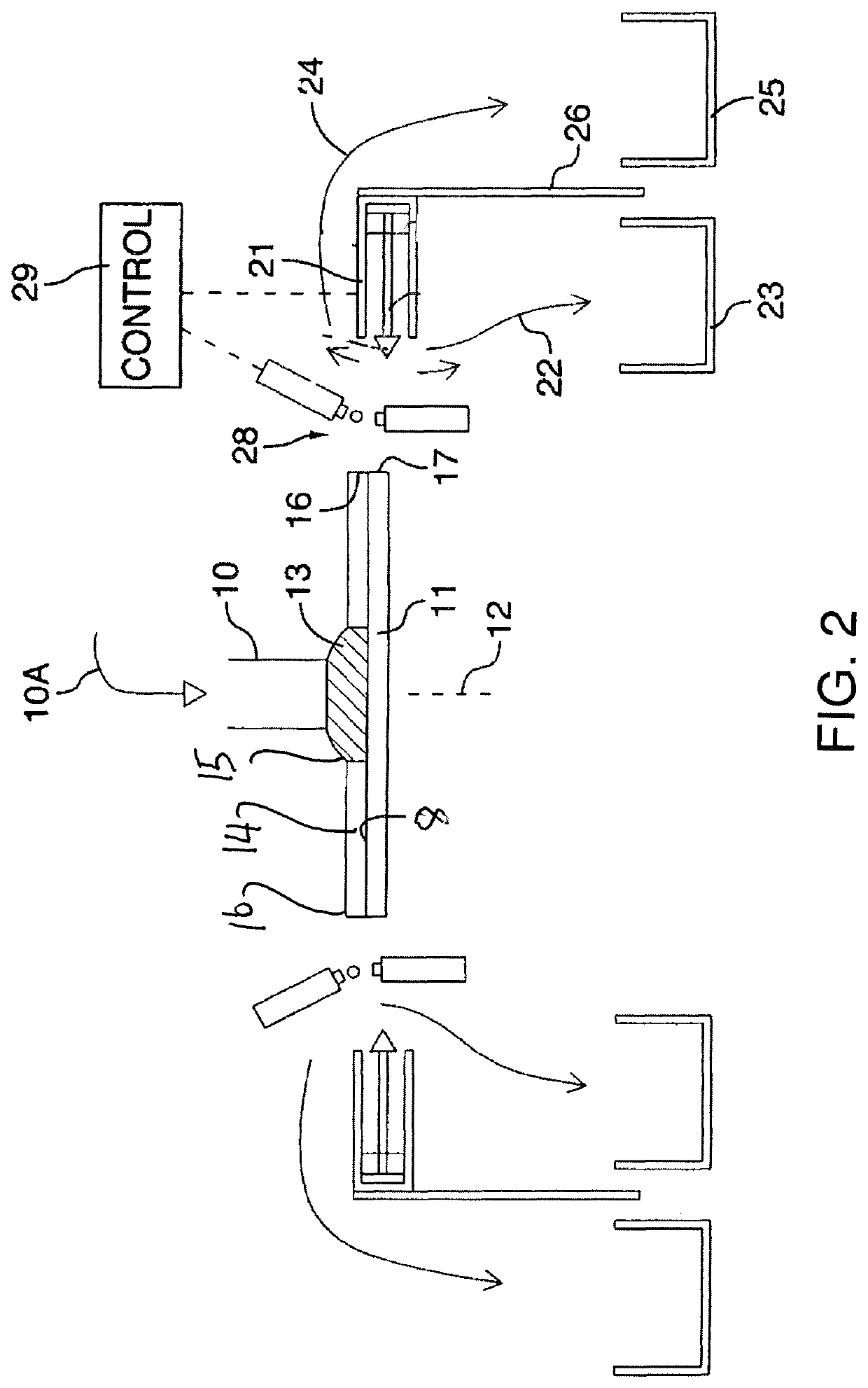
[0196]An apparatus for sorting particles based on a measurable parameter of the particles shown in FIGS. 1 and 2 comprises a supply conduit 10 carrying particles to be sorted from a feed supply 10A which supplies the particles in a continuous stream for presentation through the conduit to a rotary body 11 rotatable around an axis 12. In the embodiment shown the rotary body is a flat disk with the axis 12 arranged vertical so that the disk provides an upper horizontal surface onto which the particles 13 are supplied in the stream from the conduit 10. The conduit is arranged at the center of the disk so that the particles are deposited onto the center of the position where the disk is rotating but where there is little outward velocity. In an exemplary case, the particles may be grain kernels. The kernel velocity at this point is from the flow in the supply conduit 10. The velocity at a point on the disk is v=wr where w is the angular velocity and r is the radius. If kernels are depos...


PUM

PropertyMeasurementUnit
timeaaaaaaaaaa
wavelengthaaaaaaaaaa
phaseaaaaaaaaaa

Abstract

In a method for measuring radiation, the radiation is temporally and / or spatially separated by a modulator to direct at least N different combinations of radiation incident on each region into at least two and fewer than N distinct directions. The total intensity of radiation in each direction is measured with a detector for each modulator configuration and the detector outputs are analyzed statistically to obtain information relating to the spectral properties of the radiation. In this way substantially all of the energy received at the entrance aperture of a measurement device is encoded into multiple outputs and the multiplexed output is received by a small number of detectors.

Description

[0001]This application claims the benefit under 37USC 113 (e) of Provisional Application 62 / 510,825 filed May 25, 2017, the disclosure of which is incorporated herein by reference.[0002]This invention relates to the measurement of wave fields or particle fluxes using spatial and / or temporal modulation. The wave fields may include spatial variation in at least one characteristic or dependent variable. The invention applies to electromagnetic waves, matter waves and pressure (sound) waves. The waves may be transverse or longitudinal. The spatial variation or dependent variable in electromagnetic waves may be amplitude, intensity, frequency, wavelength, phase, polarization direction of propagation or location of origin.[0003]Electromagnetic waves may also be described as a flux of photons. Matter waves may also be described as particle fluxes of electrons, neutrons, atoms, ions, molecules, or assemblies of these. The spatial variation in particle fluxes may relate to any property of th...

Claims


Application Information

Patent Timeline
Patent Type & Authority Patents(United States)
IPC IPC(8): G01N21/86G01J3/28G01N21/65G01N21/64G01N21/35G01N27/62G01J3/00G01N21/85G01N27/447G01N21/552H01J49/40
CPCG01N21/86G01J3/28G01N2021/3595G01N27/44721G01N27/622G01J3/00H01J49/40G01N21/552G01N21/6408G01N2201/0675G01N21/65G01N21/85G01J3/021G01J3/0205G01J3/0208G01J3/0294G01J3/18G01J3/14G01J3/36G01J3/0229G01J3/2846G01J3/0237G01N27/623G01N21/35G01J3/433G01D5/48
Inventor PRYSTUPA, DAVIDPACAK, JOHN
Owner 10103560 CANADA LTD
Why Eureka
Try Eureka