
VCSEL-based resonant-cavity-enhanced atomic force microscopy active optical probe

a technology active optical probes, which is applied in the field of atomic force microscopy (afm) and nearfield optical microscopy probes, can solve the problems of inability to meet the needs of scanning probes, low efficiency and sensitivity of conventional raman spectroscopy, and large background signal, and achieve enhanced light transmission through the tip aperture, enhanced light transmission, and enhanced light transmission

Active Publication Date: 2020-05-26
ACTOPROBE LLC
View PDF4 Cites 1 Cited by
  • Summary
  • Abstract
  • Description
  • Claims
  • Application Information

AI Technical Summary

Benefits of technology

The invention is a special probe for combining AFM, NSOM, and TERS measurements. It integrates a semiconductor laser source and a specially designed atomic-force / NSOM probe into a special AFM probe holder compatible with conventional AFM. The new probe combines a light source (VCSEL) and a special aperture NSOM probe in either external-resonant-cavity or internal-resonant-cavity configuration. The fabrication process combines the well-developed technologies of AFM probe and VCSEL fabrication, resulting in a cost-effective affordable product that can be adopted for use by all current owners of atomic force microscopes. The cost advantage compared to an NSOM instrument would be on the order of 10-100 times. The invention aims to open up new important opportunities for the application of near-field optical microscopy for research and engineering in academia and industry.

Problems solved by technology

The existing Raman microscopy technology is time-consuming, difficult to use, expensive, and not available to most scientists, engineers, medical doctors and technical personnel who need to test optical / chemical properties of the sample at the nanoscale—in most cases simultaneously with conventional AFM imaging.
Conventional Raman spectroscopy is known to suffer from low efficiency and sensitivity, as it relies on the highly inefficient process of inelastic light scattering.
TERS performance, therefore, is challenged by low efficiency of coupling the laser light into the near-field mode of the optical AFM probe, leading to a tremendous optical power loss and large background signal.
TERS would greatly benefit from further sensitivity enhancement, but this cannot be achieved by simply increasing the excitation power.

Method used


Image

  • VCSEL-based resonant-cavity-enhanced atomic force microscopy active optical probe
  • VCSEL-based resonant-cavity-enhanced atomic force microscopy active optical probe
  • VCSEL-based resonant-cavity-enhanced atomic force microscopy active optical probe

Examples


embodiment 1

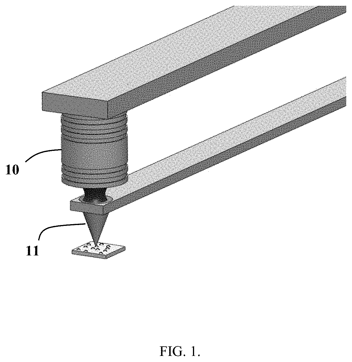
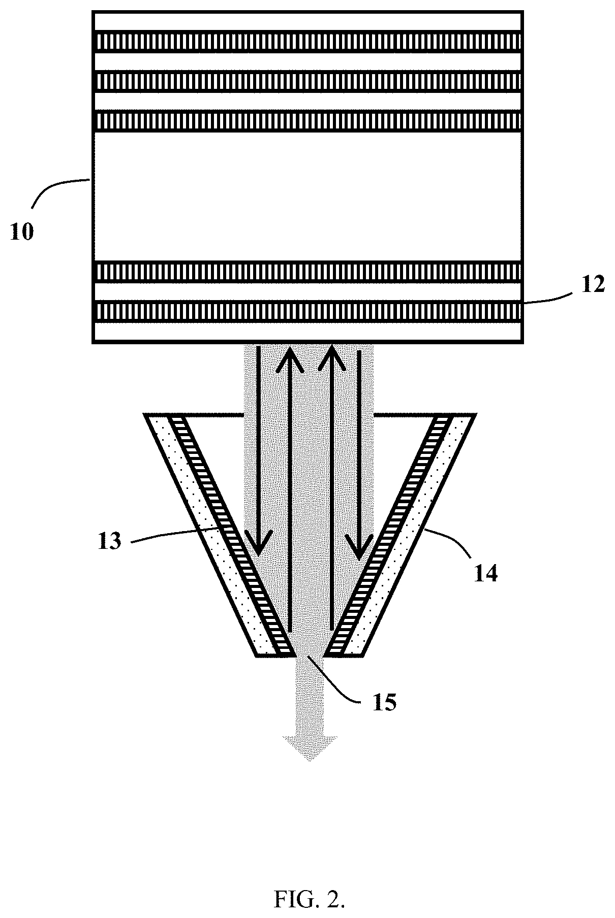
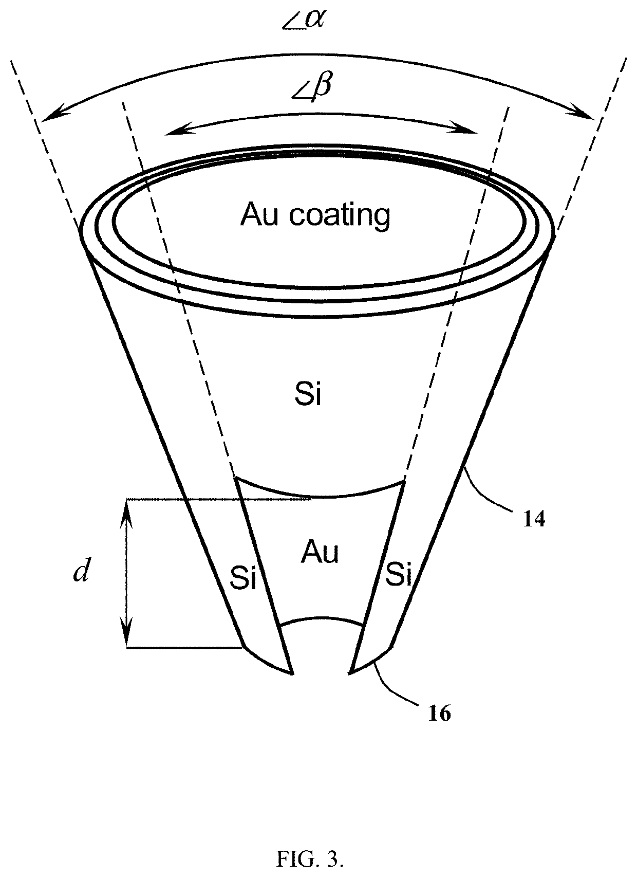
[0026]The concept of the resonant-cavity-enhanced AFM active optical probe (RCE AAOP) is illustrated in FIG. 1, where the probe combines a light source 10 (VCSEL) and a special aperture NSOM probe 11 in the external-resonant-cavity configuration. In this configuration, the top (output) DBR mirror 12 of the VCSEL 10 and the gold-coated surface 13 of the tip 14 of the special aperture NSOM probe form a high-quality external Fabry-Pérot cavity employed for enhanced transmission of light through the tip aperture 15 (FIG. 2). In this external-resonant-cavity configuration, we use the effect of external-resonance-enhanced transmission of light through sub-wavelength holes [Kalkum 2010] that allows up to 100× enhanced light transmission through the tip aperture. The large intensity of the laser light that builds up in the external cavity is efficiently transmitted through the tip aperture 15 and used for excitation of the sample at the nanoscale.

[0027]The special NSOM aperture probe may ha...

embodiment 2

[0032]In another embodiment of the present invention, the resonant-cavity-enhanced AFM active optical probe is that described in Embodiment 1, but the laser source is an optically pumped VCSEL (FIG. 6). The optically pumped VCSEL 18 generates light at the wavelength λ2 that is longer that the wavelength λ1 of the optical pumping. A special notch (band-stop) or longpass edge filter 19 is placed inside the external cavity formed by the top (output) DBR mirror 12 of the VCSEL and the gold-coated surface 13 of the tip 14 of the special aperture NSOM probe to prevent the optical pumping (light at λ1 wavelength) from reaching the surface of the sample (FIG. 6).

[0033]In the described embodiment of the present invention, NSOM and TERS measurements are enabled by applying far-field optics to collect the scattered light and direct it to a combination of an external Raman spectrometer and an external photodetector. The described embodiment is advantageous for Raman measurements that would bene...

embodiment 3

[0034]In another embodiment of the present invention, an arrangement of several commercial reverse-biased VCSEL structures are employed as near-field resonant-cavity-enhanced (RCE) photodetectors 20. They are mounted in very close proximity to a VCSEL source 10 on the same x-y-z piezo stage 21 attached to a special AFM probe holder 22 for precise positioning relative to the special aperture NSOM probe tip 14 (FIG. 7). Being an integral part of the AFM cantilever 23, the probe tip is attached to the special AFM probe holder 22 independently. The RCE photodetectors 20 are designed for detection in a narrow spectral range around the wavelength at which the VCSEL source 10 emits.

[0035]In the described embodiment of the present invention, no far-field optics is necessary for signal collection / detection. NSOM measurements are enabled in the near-field by applying the VCSEL excitation source 10 and the near-field RCE photodetectors 20 for signal detection.


PUM

PropertyMeasurementUnit
atomic force microscopyaaaaaaaaaa
AFMaaaaaaaaaa
wavelengthaaaaaaaaaa

Abstract

A new resonant-cavity-enhanced Atomic Force Microscopy (AFM) active optical probe integrates a semiconductor laser source and an aperture AFM / near-field scanning optical microscopy (NSOM) probe in either external-resonant-cavity or internal-resonant-cavity configuration to enable both conventional AFM measurements and optical imaging and spectroscopy at the nanoscale.

Description

FIELD OF THE INVENTION[0001]The present invention relates to atomic force microscopy (AFM) and near-field optical microscopy probes and, in particular, to a vertical-cavity surface-emitting laser (VCSEL)-based resonant-cavity-enhanced AFM active optical probe capable of performing both conventional AFM measurements and optical imaging and spectroscopy at the nanoscale.BACKGROUND OF THE INVENTION[0002]The existing Raman microscopy technology is time-consuming, difficult to use, expensive, and not available to most scientists, engineers, medical doctors and technical personnel who need to test optical / chemical properties of the sample at the nanoscale—in most cases simultaneously with conventional AFM imaging.[0003]Attempts at combining AFM and optical techniques have been made in the past. Combining AFM with traditional microscopy methods has become quite common, as it provides a means for simultaneous application of external forces, quantitative measurements and direct visualization...

Claims


Application Information

Patent Timeline
Patent Type & Authority Patents(United States)
IPC IPC(8): G01Q60/40G01Q60/06G01Q70/02H01S5/022G01Q70/10G01Q60/42H01S5/183H01S5/02375
CPCH01S5/02268G01Q70/02G01Q60/40G01Q60/06H01S5/183G01Q70/10G01Q60/42G01Q20/02G01Q20/04H01S5/18361H01S5/14H01S5/02375
Inventor UKHANOV, ALEXANDER A.SMOLYAKOV, GENNADY A.
Owner ACTOPROBE LLC
Learn More