High-efficiency oblique illumination system for fluorescence excitation and detection

a fluorescence excitation and fluorescence technology, applied in the field of analytical methods, can solve the problems of system wear, high heat generation, waste of polychromatic light sources, etc., and achieve the effect of increasing the excitation of a bona fide signal, not increasing the background noise signal, and quick and easy chang

Active Publication Date: 2020-07-07
PAPP ANDREW A
View PDF8 Cites 0 Cited by
  • Summary
  • Abstract
  • Description
  • Claims
  • Application Information

AI Technical Summary

Benefits of technology

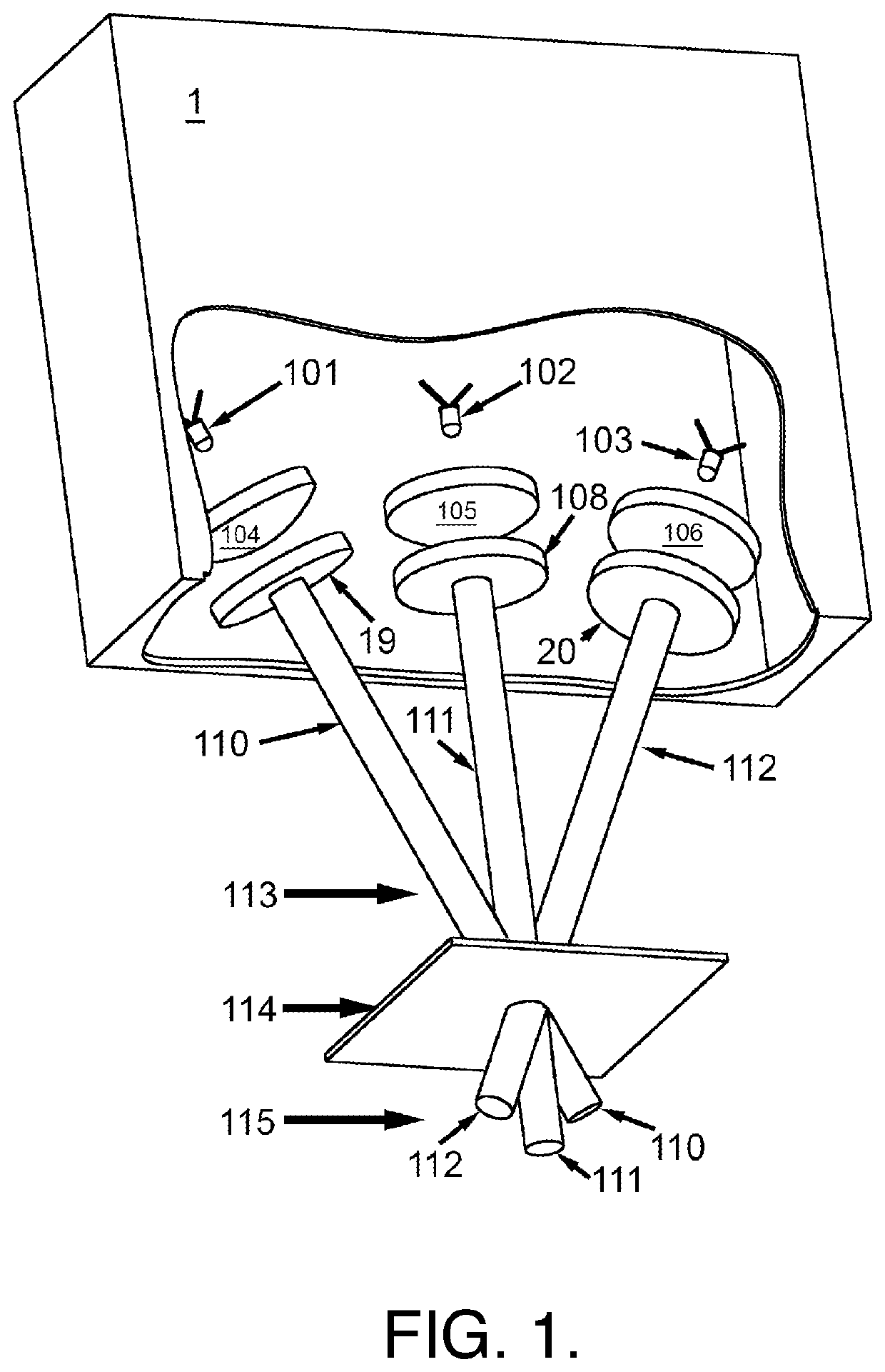
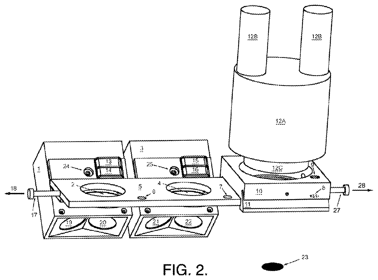
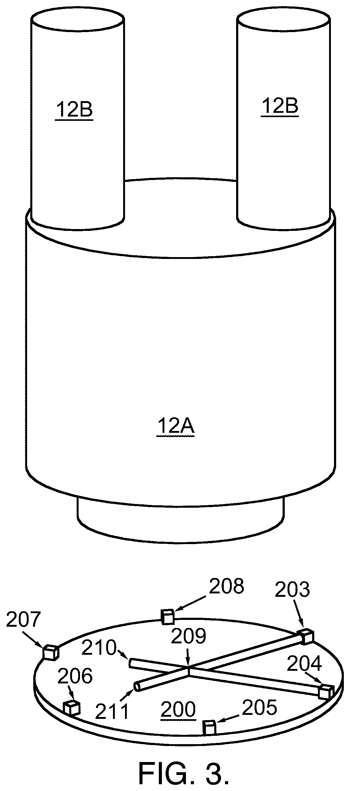
[0004]The current invention is a system that solves problems associated with using electromagnetic radiation sources, for example LEDs, to excite and analyze fluorescence. The system is a method and associated devices to practice the invention. A key feature of the invention is that it takes place independently and / or externally to any other piece of equipment. For example, if a microscope is used to observe fluorescence, the invention is located outside of the microscope and not dependent on interrupting the optical path of the microscope to excite the specimen or to filter the emission from the specimen. Elements of the invention may include the ability to rapidly and easily change between the combined excitation and analysis of different fluorophores via different modules and / or the ability to more intensely excite fluorophores through the use of modules producing multiple intersecting beams of electromagnetic radiation that converge at the specimen thus increasing excitation of a bona fide signal in the plane and location of the specimen while not increasing the background noise signal in other planes or locations.
[0005]Useful features that can contribute to the invention include the use of magnets to accurately position the modules via a moving element and the use of magnets to attach the modules to the moving element so that a user can rapidly configure the system to excite and analyze different fluorophores in different orders without the use of any tools.

Problems solved by technology

The polychromatic light source is typically an arc lamp that consumes a lot of power, generates a lot of heat, may contain toxic materials such as mercury, and is short-lived.
It relies on an inefficient, wasteful polychromatic light source, and it requires an expensive microscope specially designed for access into the light path to accommodate the cube changer system, and a cube changer system that fits a particular model of microscope.
Another challenge and shortcoming of moveable optical elements (for example the cubes) is that they must be positioned precisely, over and over as the user switches back and forth between them.
Thus, these systems are subject to wear.
Additionally, if too much force is used, such that a detent point is passed, there is nothing present to prevent the linear slider or rotary slider (turret) from moving much further.
This has all of the problems described above except that LEDs are long-lived.
Unfortunately, this system requires the use of a highly specialized microscope that both allows for epi-illumination, and additionally has provisions for powering the LEDs built into the microscope.
Furthermore, the available geometry to illuminate the specimen by epi-illumination limits illumination to one LED per cube.
This system uses only a single type of ultraviolet light LED to excite fluorescence that cannot be changed quickly and the fact that this device can mix in white light is not relevant for fluorescence detection.
The system has no provisions for quickly analyzing multiple fluorophores that require provisions for different excitation and emission spectra.
A significant drawback to prior single-colored LED direct illumination approaches is that it is nontrivial to switch between analyzing different fluorophores because LEDs, excitation filters, and emission filters, must all changed simultaneously, and prior art does not provide for this.
Another problem is that individual LEDs are often not powerful enough to excite a useful level of fluorescent signal.

Method used


Image

  • High-efficiency oblique illumination system for fluorescence excitation and detection
  • High-efficiency oblique illumination system for fluorescence excitation and detection
  • High-efficiency oblique illumination system for fluorescence excitation and detection

Examples


Embodiment Construction

[0011]The current invention solves the problems associated with using electromagnetic radiation sources such as LEDs to excite and analyze fluorescence. Throughout this patent application, reference is made to “light”, Light Emitting Diodes (“LEDs”), and “fluorescence”; however, it is to be understood that “light” is a metaphor and meant to include all electromagnetic wavelengths, including those which cannot be perceived by the human eye, and “LEDs” are just one example of a source of electromagnetic radiation (others include but are not limited to gas discharge lamps, x-ray and magnetron tubes, and a multitude of different types of lasers), and “fluorescence”, though this word typically refers to the visible or invisible radiation emitted by certain substances as a result of incident radiation of a shorter wavelength such as X-rays or ultraviolet light, in this application is expanded and refers to any detectable phenomenon that results from excited molecules, for example it could...


PUM

PropertyMeasurementUnit
peak wavelengthaaaaaaaaaa
dominant wavelengthaaaaaaaaaa

Abstract

Disclosed are a method and associated apparatus for efficiently exciting and detecting fluorescence. In a disclosed preferred embodiment, excitation lamp modules with multiple solid-state light sources shone at different oblique angles, such that multiple-beams converge in a single plane, are combined with appropriate emission filters that block the excitation light wavelengths while passing the emission wavelengths. A multitude of such modules are combined on a slider that can be accurately positioned in front of an observation point, such as a microscope's objective lens, external to the microscope, via a novel magnetic detent system, allowing for the rapid switching between the analysis of different fluorophores.

Description

BACKGROUND OF THE INVENTION[0001]There are many analytical methodologies that rely on the excitation and detection of fluorescence. For example, it is possible to determine where and when genes are expressed in a developing organism using the technique of fluorescence microscopy. A hybrid gene can be created that combines the regulatory elements of a gene of interest with the genetic coding sequences of a fluorescent protein product (a fluorophore) gene. In this case, the hybrid gene is used to create a transgenic organism such that the fluorophore will be expressed in the same cells, at the same times, as a particular endogenous gene of interest, so that one may learn where and when that gene is expressed. In order to accomplish this analysis, bright light of a particular wavelength must be shone upon the sample (this light is sometimes refined using an “excitation filter”), and the resulting excitation wavelengths must be blocked from the observer such that different and dimmer fl...

Claims


Application Information

Patent Timeline
Patent Type & Authority Patents(United States)
IPC IPC(8): G02B21/16G02B5/20G02B21/08G02B27/30
CPCG02B21/08G02B27/30G02B21/16G02B5/20
Inventor PAPP, ANDREW A.
Owner PAPP ANDREW A
Why Eureka
Try Eureka