
Low temperature arc ion plating coating

a technology of arc ion plating and coating, which is applied in the direction of coating, vacuum evaporation coating, coating, etc., can solve the problems of reducing the deposition rate of coating, ejecting a large amount of macro-particles or droplets, and affecting the performance of coating,

Active Publication Date: 2020-12-15
OERLIKON SURFACE SOLUTIONS AG PFAFFIKON
View PDF16 Cites 0 Cited by
  • Summary
  • Abstract
  • Description
  • Claims
  • Application Information

AI Technical Summary

Benefits of technology

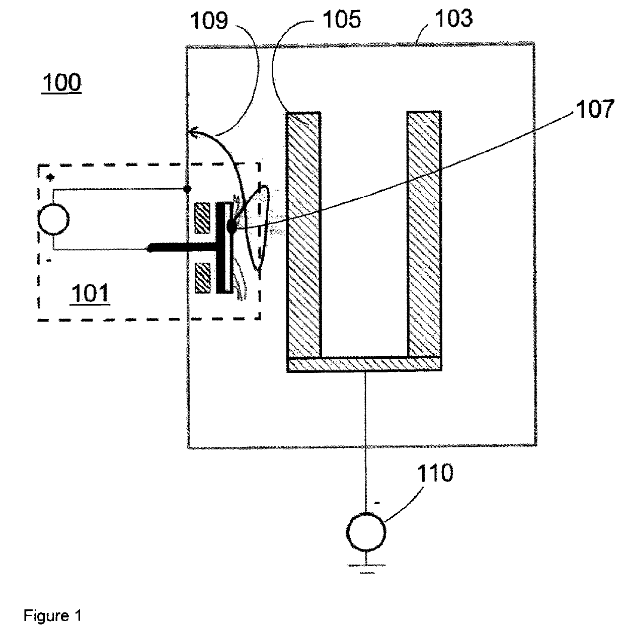
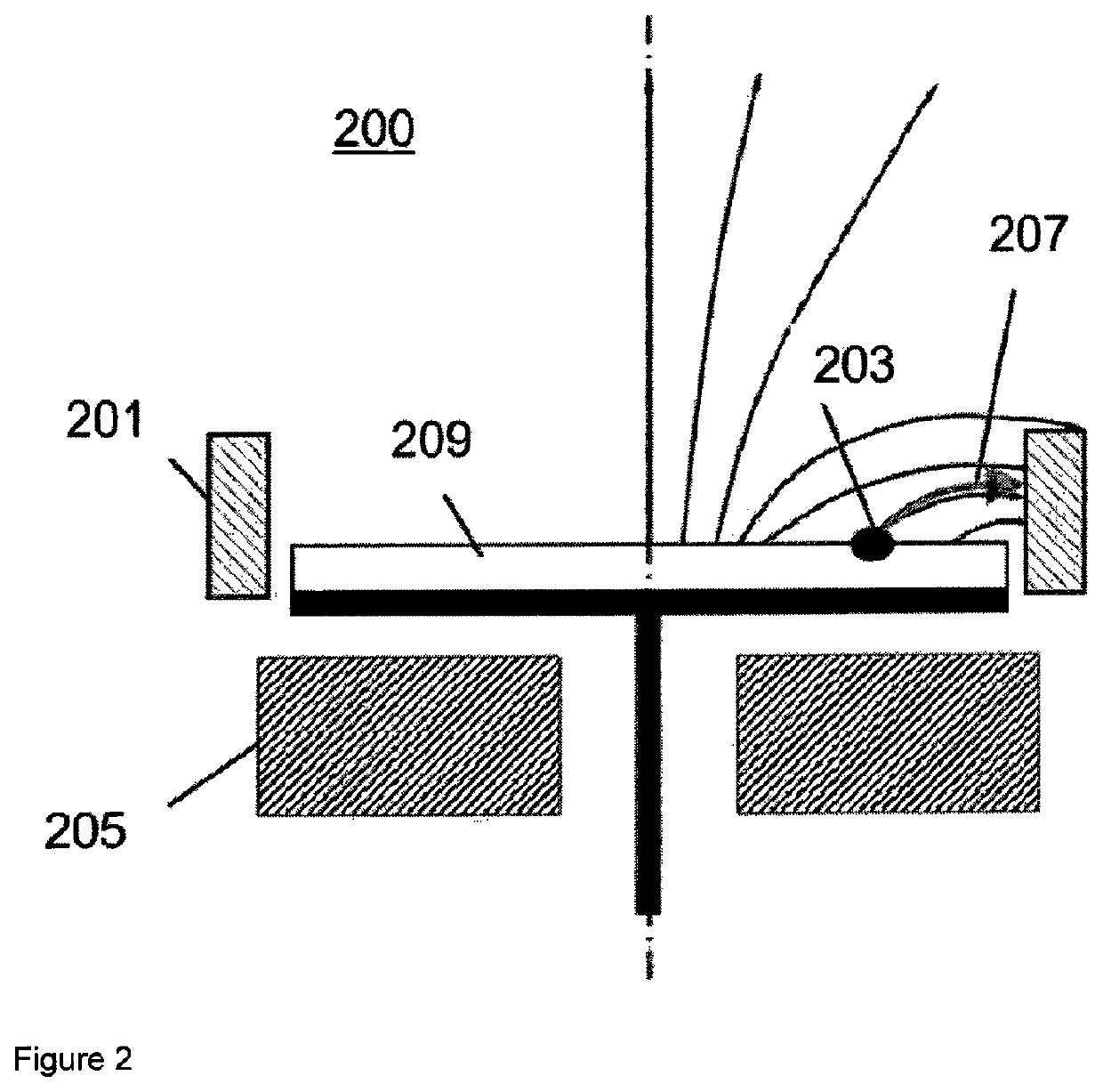
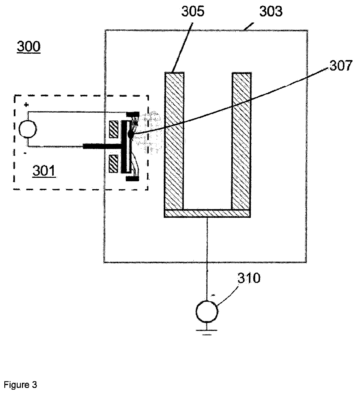
The present invention provides a low temperature arc ion plating deposition method for coating temperature sensitive substrates. This method allows the substrate temperature to maintain under 350°C, preferably under 300°C or even if necessary between 100°C and 300°C or lower. The thin films produced by this method exhibit smooth surface and excellent mechanical properties, and they also have a similar coating quality to equivalent thin films deposited at higher substrate temperatures. The coating method allows deposition rates that are equal to those obtained by higher substrate temperatures. Additionally, higher coating densities, enhanced mechanical properties, and even increased hardness of certain coating systems can be obtained by applying determinate bias voltages. High magnetic field intensities are especially good for producing coating films with reduced droplets amount and size and with lower roughness. The use of high magnetic field intensities leads to increased plasma discharge voltages and higher ionization of the process gas, which results in increased heat energy into the substrate and higher substrate temperatures. The present invention helps to avoid a prominent spiral motion of the charged particles by flowing from the cathode to the substrate.

Problems solved by technology

One downside of the arc evaporation process is however that if the cathode spot stays at an evaporative point for too long time it can eject a large amount of macro-particles or droplets.
These droplets are detrimental to the performance of the coating as they are poorly adhered and can extend through the coating.
This action involves an associated and unavoidable reduction of the coating deposition rate what is disadvantageous.Don't applying a bias voltage or applying a reduced bias voltage at substrate during coating process.
This action is also disadvantageous because the produced coatings exhibit lower density and in general inferior mechanical properties.Removing of heat energy from the substrate continuously during coating process.
This action can be very complex and expensive.Don't using magnetic fields or using weakly magnetic fields or rather low magnetic field intensities.
This action involves the disadvantage that the cathode spot moves slower on the target surface and consequently remains for longer time at each evaporative point which leads to ejection of a larger amount of macro-particles or droplets.

Method used


Image

  • Low temperature arc ion plating coating
  • Low temperature arc ion plating coating
  • Low temperature arc ion plating coating

Examples


example 1

[0069]The inventors accomplished three variants of the same coating process in order to compare the electric potential values of the generated coating plasma discharges. Following coating process parameters were fixed and maintained constant by all of the three analyzed coating process variants:[0070]Process gas: N2 [0071]Target composition: Ti:Al 50:50 at %[0072]Arc current at target (IARC): 200 A[0073]Number of activated targets by coating: 1[0074]Intensity of the used magnetic field was about 60 Gauss[0075]Bias voltage: 0 V[0076]Process gas flow and bias voltage were equal for other process variants and in all the cases were maintained constant during coating process.

[0077]Potential difference between cathode and anode (UARC) as well as overall yield of heat energy transferred to cooling fluid (QTOTAL) was measured. Total introduced electric power in coating process (PTOTAL) was calculated multiplying UARC and IARC (PTOTAL=UARC×IARC). The overall yield of heat energy transferred ...

example 2

[0080]Two kind of AlCrN coating films were deposited by using same coating parameters but a first time using an anode arranged according to the state of the art and a second time using an anode arranged according to the present invention. Both coating films exhibited very good coating quality and essentially same coating properties. The only clear difference was the substrate temperature attained by these coating processes. In the first case the maximal substrate temperature attained by coating was about 475° C., while by coating in the second case a maximal coating temperature of 210° C. was attained. That verified a stupendous diminution of the substrate temperature as it is shown in FIG. 5.

[0081]In both cases 1 and 2 a constant arc current per target of 150 A was used during coating.

[0082]The bias voltage was also identical in both cases 1 and 2. Two different bias voltage values were set during coating, as it is shown in FIG. 6, in order to analyze the influence of this paramete...


PUM

PropertyMeasurementUnit
temperatureaaaaaaaaaa
temperaturesaaaaaaaaaa

Abstract

Coating method for arc coating or arc ion plating coating of substrates in a vacuum chamber in which using an arc evaporator solid material that functions as cathode is evaporated, during arc evaporation the motion of the cathode spot on the solid material surface is accelerated using a magnetic field for avoiding ejection of a large amount of macro-particles or droplets from the solid material surface, negative charged particles resulted from the arc evaporation flow from the cathode to an anode, characterized by the motion of the negative charged particles from the cathode to the anode fundamentally doesn't cause an additional increase of the absolute value of the potential difference between cathode and anode allowing a lower increment of the substrate temperature during coating.

Description

[0001]The present invention relates to a low temperature arc ion plating (AIP) deposition method for producing thin films which exhibit smooth surface and excellent mechanical properties.STATE OF THE ART[0002]The AIP technique is one of the most common physical vapor deposition (PVD) coating processes characterized by using cathodic arc sources for the evaporation of the coating material in vacuum conditions (working pressure about 10−2 to 10−4 mbar). By cathodic arc deposition a high power electric arc discharged at the target (material source) results in the evaporation of some target material and hence a highly ionized vapor is provided to be deposited onto the substrate.[0003]The term IP (ion plating) refers to the bombardment of the substrate to be coated with energetic positively charged ions during coating process, which can be achieved by applying a bias voltage at the substrate. It promotes the condensation of high density coatings on the substrate. Additionally, reactive g...

Claims


Application Information

Patent Timeline
Patent Type & Authority Patents(United States)
IPC IPC(8): C23C14/34C23C14/32H01J37/32
CPCC23C14/325H01J37/32055C23C14/345H01J37/32568H01J37/32C23C14/32
Inventor KRASSNITZER, SIEGFRIEDKURAPOV, DENISLECHTHALER, MARKUS
Owner OERLIKON SURFACE SOLUTIONS AG PFAFFIKON
Learn More