

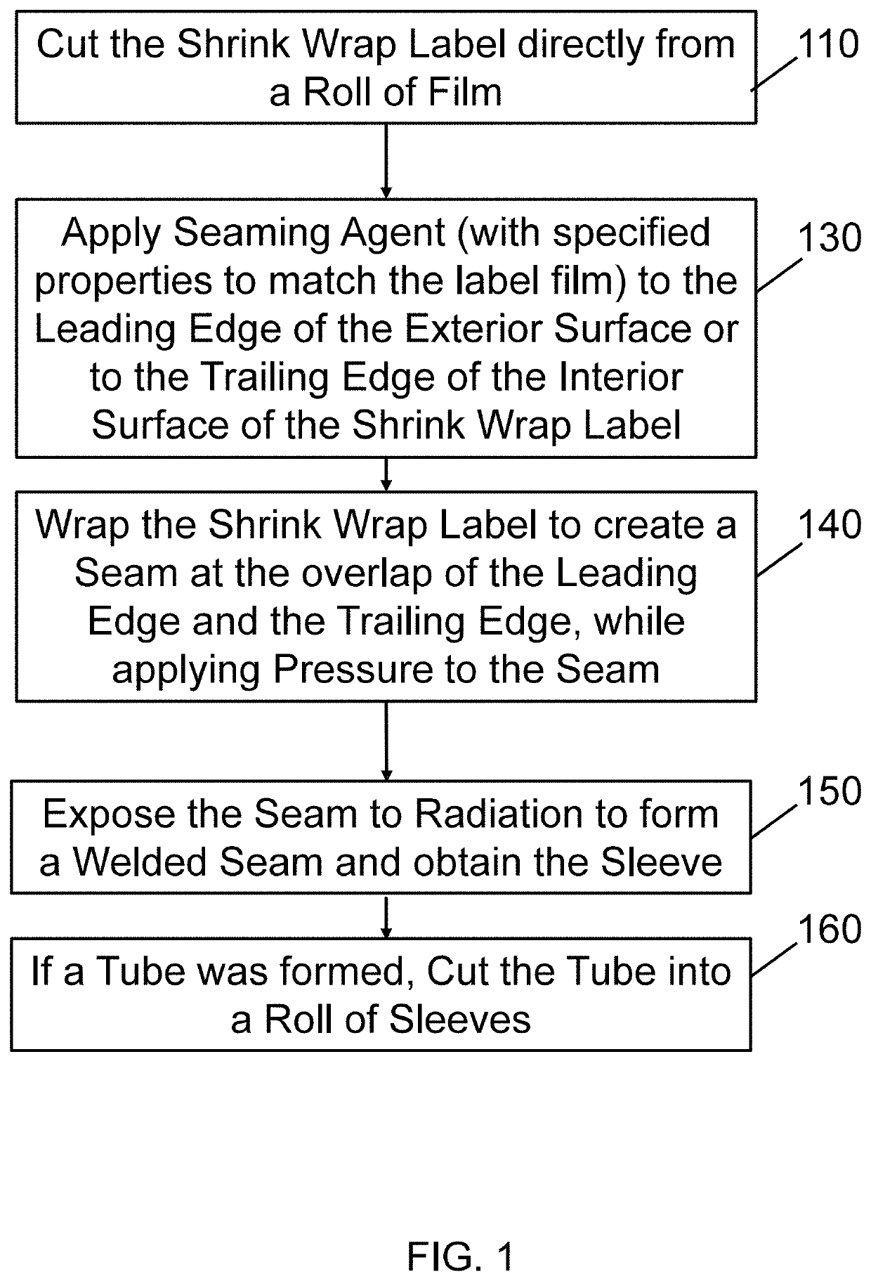
Methods for forming high shrink wrap label sleeves
a label and label technology, applied in the direction of labelling, short rigid containers, labelling, etc., can solve the problems of voc emission very high, the sleeves are tightly pressed against the containers, and the method is limited to less than 200 containers per minute, so as to reduce voc emissions and high shrinkage
- Summary
- Abstract
- Description
- Claims
- Application Information
AI Technical Summary
Benefits of technology
Problems solved by technology
Method used
Image

Examples
example 1
[0169]FIGS. 5-11 are pictures / photographs illustrating a test of the methods of the present disclosure. A high shrink wrap label is wrapped around a mandrel to simulate the methods.
[0170]FIG. 5 is a first picture of the test. The label is placed on a vacuum plate. The vacuum plate simulates the vacuum drum on a roll fed machine.
[0171]FIG. 6 is a second picture of the test. The label is picked by the vacuum plate.
[0172]FIG. 7 is a third picture of the test. Seaming agent is applied on trailing edge by 6 mm wide brush, calibrated to apply 0.2-2 mg seaming agent per square centimeter seam.
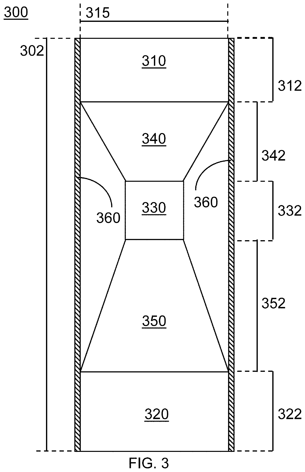
[0173]FIG. 8 is a fourth picture of the test, showing a curved mandrel pressed against the leading edge of the label. (The mandrel is as illustrated in FIG. 3.) Two dots of tacky low melting point pressure sensitive adhesive (pick up glue) were deposited on the top and bottom parts of leading edge of label for ease of testing.
[0174]FIG. 9 is a fifth picture of the test, showing the label wrapped aroun...
example 2
[0177]Eight different seaming agents E1-E8 were tested for their ability to establish a clear and durable seam after being pressed between two rolls. They were also tested for their ability to weld different materials, and for their immediate welding strength, as well as to provide a seam with a seam quality of at least 2 after heat shrinkage at 0-60% shrinkage. They were made with varying amounts of MIRAMER M200, MIRAMER M600, MIRAMER M3130, tetrahydrofurfuryl acrylate (THFA), isobornyl acrylate (IBOA), and GENOMER 6043 / M22 (a blend of monomer and saturated polyester blend of oligomers and polymers).
[0178]MIRAMER M200 is a semi-polar difunctional monomer (Hexanediol diacrylate) manufactured by Rahn with very low viscosity (6-12 cPs at 23° C. and low molecular weight of 226 Da). MIRAMER M200 has good compatibility with PVC and PS, is partially compatible with PETG, and is incompatible with COC.
[0179]MIRAMER M600 manufactured by Rahn is a semi-polar hexafunctional oligomer (dipentaer...
example 3
[0208]In order to demonstrate the correlation between seam quality and immediate welding strength, an immediate welding strength test was conducted on seaming agents E1-E8. FIGS. 12-15 illustrate how an immediate welding strength test was performed using two strips with a width of 25 mm, a length of 200 mm, and a seam made from a 10 mm overlap on the strip. A device with two pistons was used.
[0209]FIG. 12 is a first picture illustrating the immediate welding strength test. A first strip of 25 mm wide, made of a high shrink film, is used to simulate leading edge of the label, attached to a vacuum drum and clamped by first right clamp.
[0210]FIG. 13 shows the leading edge wrapped around the vacuum drum and clamp pressed to keep the first strip from moving.
[0211]FIG. 14 is a third picture of the immediate welding strength test, showing a second strip of same film type and width (simulating the trailing edge) being held by the left piston of the test device. One edge of the second strip ...
PUM
| Property | Measurement | Unit |
|---|---|---|
| temperature | aaaaa | aaaaa |
| viscosity | aaaaa | aaaaa |
| viscosity | aaaaa | aaaaa |
Abstract
Description
Claims
Application Information