
Gas sensor, measuring element for a gas sensor and method for preparing a measuring element

a technology of gas sensor and measuring element, which is applied in the field of gas sensor, can solve the problems of insufficient robustness of sensors for some applications, limited free space available for correspondingly mounted sensors, and inability to reliably measure, etc., and achieves the effects of reducing energy consumption, improving sensitivity, and improving mechanical robustness

Active Publication Date: 2021-06-15
DRAGER SAFETY
View PDF19 Cites 0 Cited by
  • Summary
  • Abstract
  • Description
  • Claims
  • Application Information

AI Technical Summary

Benefits of technology

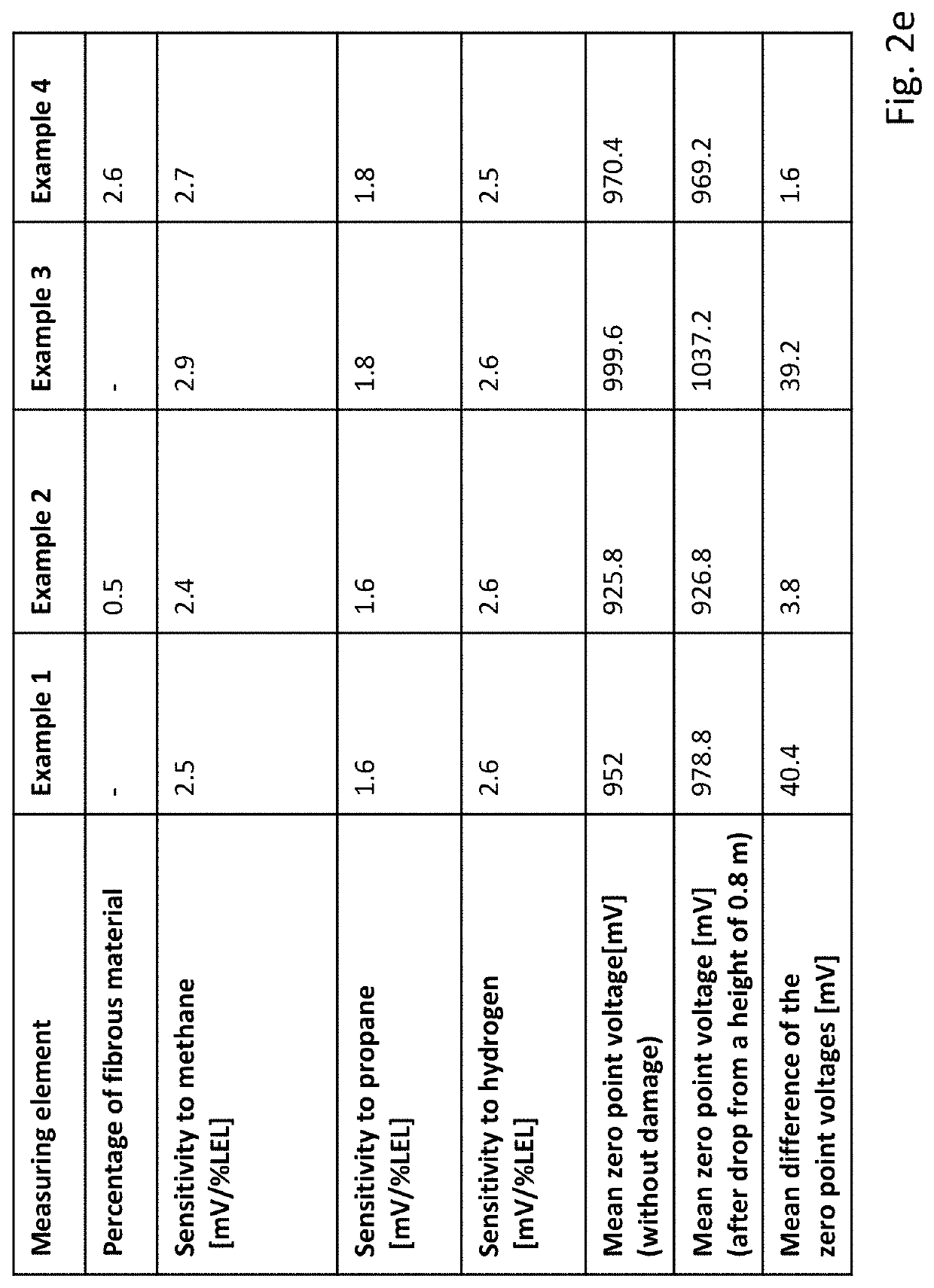
The present invention aims to create an improved gas sensor and measuring element for gas sensors that have greater mechanical robustness, lower energy consumption, and higher sensitivity to gases. The gas sensor and measuring element should also be simple and cost-effective to prepare. The invention proposes using fibrous materials, such as glass fibers, microfibers, or nanofibers, as the measuring element for the gas sensor. These fibrous materials should be non-electrically conductive, flexible, and able to be distributed randomly in the ceramic. The heating coil, which is the part of the gas sensor that generates the gas sensor signal, should be made of a noble metal or a noble metal alloy, such as platinum, palladium, or rhodium, which has a high temperature coefficient of resistance. The ceramic should also contain nanoparticles as a support, which can enhance the catalytically active surface of the measuring element. The percentage of fibrous material relative to the ceramic should be at least 0.1% and preferably at least 0.5% or more. The invention also proposes a method for preparing the gas sensor and measuring element.

Problems solved by technology

However, one problem that is associated with these sensors is the fact that these sensors lack an absolutely sufficient robustness for some applications.
If the sensor is subject to high mechanical loads, the problem may arise that the Pellistor bead will be damaged, so that reliable measurement is no longer possible.
It may, however, be disadvantageous in this case that, especially in case of a compact design of the gas-measuring device, only a limited free space is available for a correspondingly mounted sensor to move.
In addition, this design may prevent hermetic sealing of the interior of the gas-measuring device.
As a consequence, interfering gases from the interior of the gas-measuring device may prove to be problematic.
Even though the measuring element is protected here rather well against mechanical effects, the construction is relatively complicated and an undesired removal of heat may occur through the additional support wire.
Even though the bead is protected here as well, the feeding of the gas to be analyzed to the Pellistor bead, especially to the catalytically active surface of the bead, may be hindered by the shock-absorbing material, so that these sensors are possibly only suitable for a limited selection of gases and environments.

Method used


Image

  • Gas sensor, measuring element for a gas sensor and method for preparing a measuring element
  • Gas sensor, measuring element for a gas sensor and method for preparing a measuring element
  • Gas sensor, measuring element for a gas sensor and method for preparing a measuring element

Examples


example 1

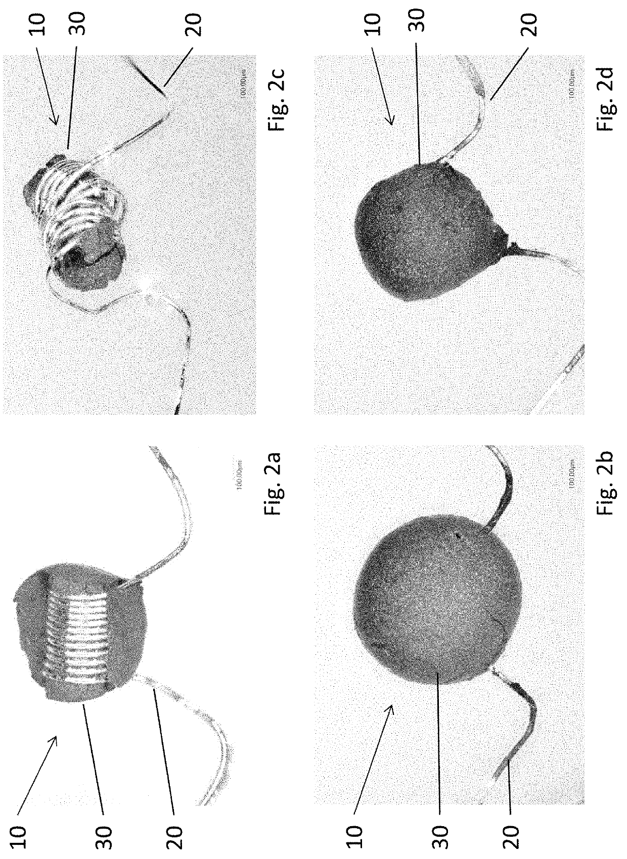
[0051]To prepare a measuring element 10, as it can be seen in FIG. 2a, 2g of tris(ethylenediamine) rhodium(III) trichloride hydrate (Alfa Aesar, 10553) are dissolved in 10 mL of distilled water while stirring at approx. 50° C. Then, 200 mg of aluminum oxide (BDH Chemicals, 33138 2S) and 100 mg of zirconium dioxide (Sigma Aldrich, 544760) are added to 1 mL of the solution obtained and suspended in an ultrasonic bath for 10 minutes. The suspension is subsequently applied step by step to a platinum coil (diameter 25 μm, Heraeus), which forms the heating coil 20. Each step of application is followed by a drying step by sending a heating current of 70 mA through the platinum wire. The bead obtained in the preceding steps is calcined after the last coating and drying operation by setting the operating current of 115 mA. The rhodium salt, which is contained as a catalyst precursor in the coating solution, is converted now into rhodium oxide.

example 2

[0052]Glass fibers are provided as fibrous material to prepare a measuring element 10 according to the present invention with a corresponding ceramic 30. Commercially available glass fibers may be used, or the glass fibers are prepared from glass fiber mat as follows: 0.5 g of glass fiber mat (Munktell, MK360) is chopped into small pieces and added to 50 mL of distilled water. The glass fibers are then stirred gently for 24 hours, so that they can swell. The swollen mass of glass fiber mat, in which the glass fibers are present randomly and freely, is then dried at 60° C. for about 6 hours.

[0053]As was already described for Example 1, a suspension of 1 mL of tris(ethylenediamine) rhodium(III) trichloride solution, to which aluminum oxide and zirconium oxide were added, is then prepared and mixed with 2 mg of the dried glass fibers. The coating solution thus prepared is treated in an ultrasonic bath for 10 minutes. The suspension is then applied, as was likewise described for Example...

example 3

[0055]To prepare an alternative measuring element 10, which likewise corresponds to the state of the art, 2 g of tris-ethylenediamine) rhodium(III) trichloride hydrate (Alfa Aesar, 10553) are again dissolved in 10 mL of distilled water while stirring at approx. 50° C. Then, 200 mg of aluminum oxide (BDH Chemicals 33138 2S) and 75 mg of cerium oxide (Sigma Aldrich, 544841) are added to 1 mL of the solution obtained and suspended in an ultrasonic bath for 10 minutes. The further procedure is carried out as described already for Example 1 in this case as well.


PUM

PropertyMeasurementUnit
operating temperaturesaaaaaaaaaa
diameteraaaaaaaaaa

Abstract

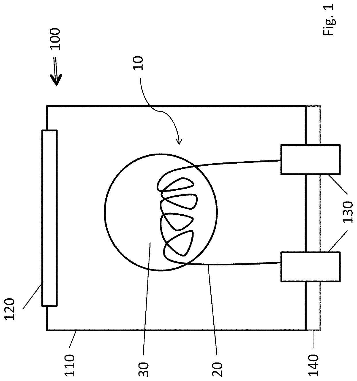
A gas sensor 100 includes a housing 110 and with a measuring element 10. The measuring element 10 has a heating coil 20, which is coated with a catalytically active or inactive ceramic 30. The ceramic 30 contains a fibrous material. The fibrous material may be, for example, a glass fiber material.

Description

CROSS REFERENCE TO RELATED APPLICATIONS[0001]This application claims the benefit of priority under 35 U.S.C. § 119 of German Patent Application 10 2014 018 681.4 filed Dec. 18, 2014, the entire contents of which are incorporated herein by reference.FIELD OF THE INVENTION[0002]The present invention pertains to a gas sensor with a housing and with a measuring element, wherein the measuring element has a heating coil, which is coated with a catalytically active or inactive ceramic, as well as to a measuring element for a gas sensor wherein the measuring element has a heating coil, which is coated with a ceramic and to a method for preparing a measuring element.BACKGROUND OF THE INVENTION[0003]Gas sensors are typically used to monitor industrial processes, in which combustible gases and vapors may be present at rather high concentrations even during normal operation. Especially so-called heat tone sensors are widely used in this connection for monitoring explosive atmospheres. Such heat...

Claims


Application Information

Patent Timeline
Patent Type & Authority Patents(United States)
IPC IPC(8): G01N27/14G01N27/16G01D11/24C04B35/82
CPCG01D11/245C04B35/82G01N27/16
Inventor DITTRICH, MIRIAMSTENDER, ERIKOSSWALD, JÜRGEN
Owner DRAGER SAFETY
Learn More