Pseudo-piezoelectric d33 vibration device and display integrating the same

a technology of pseudo-piezoelectric d33 and vibration device, which is applied in the direction of static indicating device, mechanical vibration separation, instruments, etc., can solve the problems of contaminating pzt, unable to easily micro-manufacture, and inability to easily integrate pvdf etc., to achieve easy integration with the semiconductor manufacturing process, low cast, and easy processing

Active Publication Date: 2021-07-13
MAY SUN TECH CO LTD
View PDF31 Cites 0 Cited by
  • Summary
  • Abstract
  • Description
  • Claims
  • Application Information

AI Technical Summary

Benefits of technology

[0007]An objective of this disclosure is to provide a pseudo-piezoelectric d33 vibration device with the advantages of easy integration with the semiconductor manufacturing process, easy processing and low cast but without contamination.
[0010]With the above-mentioned aspects of this disclosure, a pseudo-piezoelectric d33 structure functioning as a vibration-type transceiver and having functions the same as the piezoelectric vibration element can be provided without utilization of the piezoelectric material. More particularly, integration with the semiconductor manufacturing process and the integrated circuit element becomes possible without temperature limitations and contamination problems. Meanwhile, only the standard voltage, such as 3.3 volts or 5 volts, is needed upon operation, thereby significantly increasing system integration simplicity.

Problems solved by technology

Upon manufacturing, PVDF is engineering plastic, processes of exposure, development and the like cannot be easily performed by adopting semiconductor manufacturing process, such as lithography and the like, and the processing usually only can rely on laser processing, for example.
Therefore, it is very problematic to integrate the PVDF with the semiconductor manufacturing process.
PZT is contaminating and cannot be micro-machined easily, and the d33 operation mode cannot be implemented until the bulk or block material is used (e.g., the thin film PZT is operated in the d31 mode).
Such PZT is usually produced by way of sintering at the high temperature ranging from 700 to 800° C., or even 1000° C. Therefore, the conventional d33 PZT elements are discrete elements, and integration with the semiconductor manufacturing process becomes very difficult or even impossible so that the piezoelectricity element cannot be integrated with the integrated circuit.
Also, the lead contaminates the semiconductor device.
Furthermore, PZT needs the platinum electrodes, so that the manufacturing cost is high.
Such high voltage encounters a problem upon system integration, and a big problem upon integration with the semiconductor manufacturing process.

Method used


Image

  • Pseudo-piezoelectric d33 vibration device and display integrating the same
  • Pseudo-piezoelectric d33 vibration device and display integrating the same
  • Pseudo-piezoelectric d33 vibration device and display integrating the same

Examples


Embodiment Construction

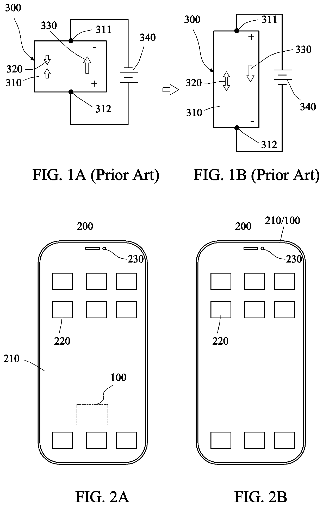
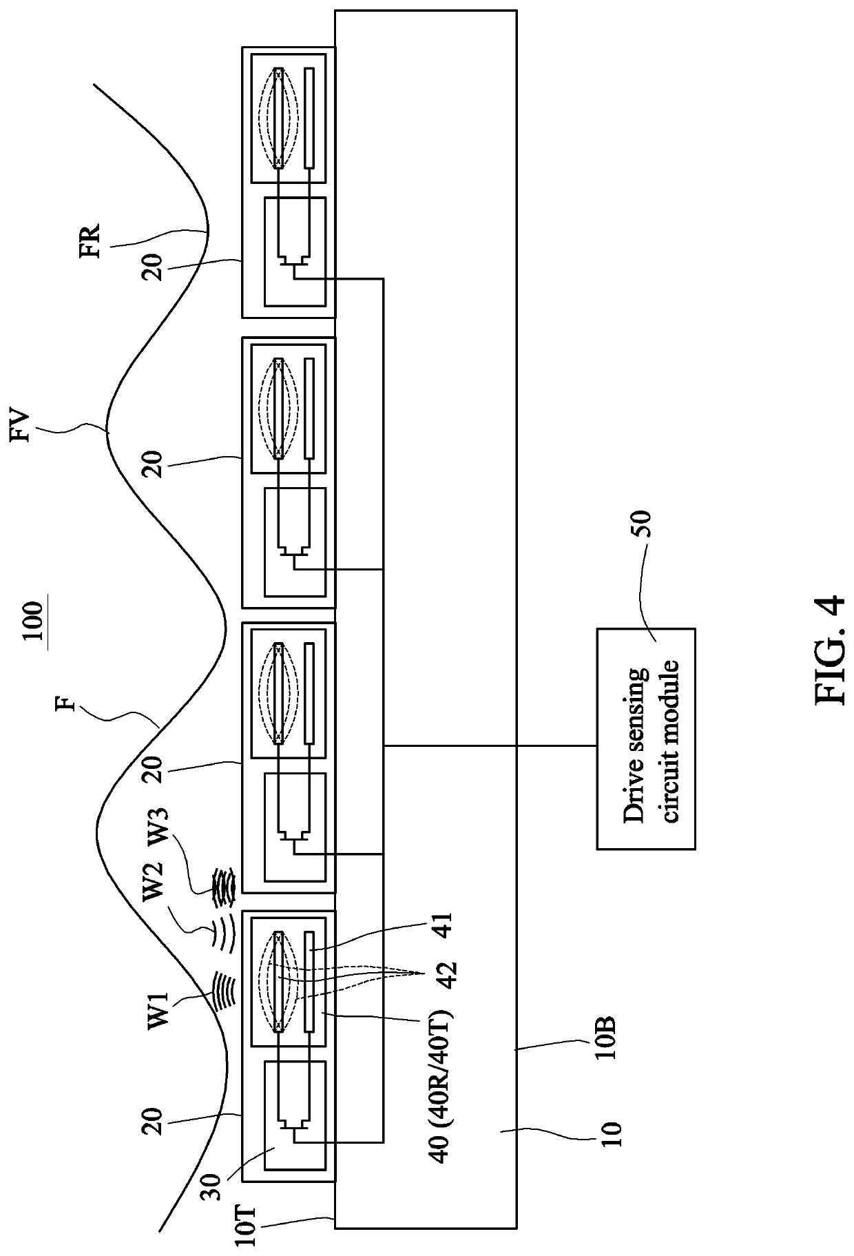
[0028]The pseudo-piezoelectric d33 vibration device provided in the embodiment of this disclosure is not made of the piezoelectric material, but uses a vibration structure having a vacuum-gap-containing or air-gap-containing membrane structure to achieve the transceiving function of making the applied electric field direction be the same as the vibration direction. The term “d33” is usually based on the piezoelectric material. In this disclosure, the conventional piezoelectric material is replaced with a micro-structure, so the vibration-type transceiver of this disclosure is named as the pseudo-piezoelectric d33 vibration device to simulate behaviors of the bulk piezoelectric material.

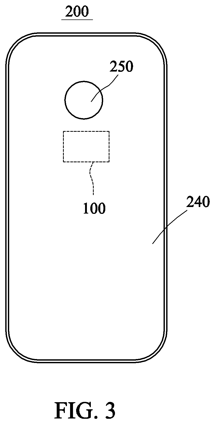
[0029]FIGS. 2A, 2B and 3 show schematic views of three applications of a pseudo-piezoelectric d33 vibration device 100 according to a preferred embodiment of this disclosure. However, the system application of the device of this disclosure is not restricted thereto. In FIG. 2A, the vibration device 10...


PUM


Abstract

A pseudo-piezoelectric d33 vibration device includes transistors and receivers electrically connected to the transistors. Each transistor controls a corresponding one of the receivers to receive a second vibration wave, generated after an object reflects a first vibration wave, and to generate a sensing signal. Each receiver has a first electrode, a second electrode and a nano-gap, which is created between the first and second electrodes after a semiconductor-metal compound is formed. A display integrating the pseudo-piezoelectric d33 vibration device is also provided.

Description

CROSS-REFERENCE TO RELATED APPLICATIONS[0001]This application claims priorities of Nos. 108115346; 108128509; and 109102411 respectively filed in Taiwan R.O.C. on May 3, 2019; Aug. 12, 2019; and Jan. 22, 2020 under 35 USC 119, the entire contents of which are hereby incorporated by reference.BACKGROUND OF THE INVENTIONField of the Invention[0002]This disclosure relates to a pseudo-piezoelectric d33 vibration device and a display integral the same, and more particularly to a pseudo-piezoelectric d33 vibration device, which has an integrated transceiver and is applicable to various electronic devices, apparatuses and systems, and relates to a display integrating the transceiver.Description of the Related Art[0003]A conventional vibration-type transceiver, sensor or transducer, such as sonic or ultrasonic transceiver, can be used for measurement of medical organ images, gesture detection, three-dimensional touch, fingerprint sensing, subcutaneous bioinformation (capillary information, ...

Claims


Application Information

Patent Timeline
Patent Type & Authority Patents(United States)
IPC IPC(8): G06F3/044G06F1/16G06K9/00H01L41/047H01L41/113
CPCG06F3/0445G06F1/1652G06K9/0002H01L41/0471H01L41/1132G06F2203/04102G06F2203/04111H03H9/2405G09G3/20G06F3/0412G06F2203/04108G06V40/1306G06V40/10G06V40/14B06B1/0622H10N30/87H10N30/50H10N30/85H10N30/302H10N30/871
Inventor CHOU, BRUCE C. S.
Owner MAY SUN TECH CO LTD
Why Eureka
Try Eureka