High aspect ratio weld face design for dissimilar metal welding

a technology of high aspect ratio and welding face, which is applied in the direction of resistance electrode holders, welding apparatus, manufacturing tools, etc., can solve the problems of difficult to effectively control and concentrate heat within the aluminum workpiece, difficult to spot welding an aluminum workpiece to a steel workpiece, and source of near-interface defects in the growing weld pool. , to achieve the effect of improving peel strength, improving overall structural integrity, and less prone to affect the mechanical properties of the weld join

Active Publication Date: 2021-07-20
GM GLOBAL TECH OPERATIONS LLC
View PDF7 Cites 0 Cited by
  • Summary
  • Abstract
  • Description
  • Claims
  • Application Information

AI Technical Summary

Benefits of technology

[0012]The welding face of the steel welding electrode, to engage the outer surface of the steel workpiece, is shaped to fit into a narrow spot welding surface while delivering a suitable welding current to the stack-up. But the subject steel welding electrode may be used in other aluminum alloy / steel stack-ups in which it is helpful to manage the Fe—Al intermetallic layer. The weld face of the steel welding electrode is not circular and its shape will have an aspect ratio greater than one (preferably greater than 1.5). For example, the plan-view shape of the weld face of the steel welding electrode may be rectangular, or elliptical, or shaped like an oval with straight long sides (race track), or like a circle with one or more parallel slices removed. Thus, the weld face of the steel welding electrode has a narrow portion and a long portion. Suitably, the minimum dimension (narrow portion) of the steel welding electrode weld face is about 1.5 mm and the maximum dimension (long portion) is about 16 mm (the suitable maximum dimension of the round body of the steel welding electrode) and preferably 2 mm (min) by 10 mm (max). For example, the steel workpiece engaging face of the steel welding electrode may be generally rectangular, with dimensions of 3.5 mm by 10 mm. Thus, it will have an aspect ratio greater than one (AR=2.8). This high aspect ratio weld face on the steel welding electrode will lie at the top or end of a tapered portion extending from the round base of the electrode. In some applications the weld face will be off-center or tilted. The orientation of the high aspect ratio weld face on the steel welding electrode will lie such that it fits into the narrow width portion on the steel workpiece in which the resistance weld is to be carefully located. It is also believed that by limiting the width of the weld face of the steel welding electrode, useful asymmetric fusion zones may be produced. These should result in thinner and higher strength Fe—Al intermetallic regions that can help welding if difficult welding stack-ups where high strength is required at the aluminum-to-steel interface. The high aspect ratio welding faces on the steel welding electrode can also serve well in welding through an adhesive layer applied to the interface by providing a shorter path for adhesive to escape from beneath the welding electrodes during the welding process.
[0015]The differing shapes of the respective welding electrode weld faces and the difference in current density between the steel and aluminum alloy workpieces (greater current density in the steel workpiece) concentrates heat within a smaller zone in the steel workpiece as compared to the aluminum alloy workpiece. The weld current schedule can even be regulated, if desired, to initiate a molten steel weld pool within the bulk of the steel workpiece(s) without the molten steel contacting the molten aluminum, in addition to initiating the molten aluminum alloy weld pool within the aluminum alloy workpiece(s) and at the faying interface. The act of concentrating heat within a smaller zone in the steel workpiece—possibly to the extent of initiating a molten steel weld pool—modifies the temperature gradients and, thereby, the solidification behavior of the molten aluminum alloy weld pool. These thermally-induced effects can result in a weld joint at the faying interface that has improved peel strength and better overall structural integrity.
[0016]In particular, the belief is that concentrating heat within a smaller zone in the narrow portion of the steel workpiece(s) as compared to the aluminum alloy workpiece(s) causes temperature gradients to be formed within and around the molten aluminum alloy weld pool, allowing the weld pool to solidify from its outer perimeter towards its central region at the weld site interface more effectively than if a round, AR=1, weld face were employed by the steel welding electrode This solidification would be driven in the direction of the short (or narrow) axis of the weld face for the steel welding electrode. A solidification front that moves inwards from the weld pool perimeter towards the center of the weld pool, in turn, drives weld defects, such as gas porosity, shrink porosity, micro-cracks, and oxide film remnants, toward the center of the weld joint where they are less prone to affect the mechanical properties of the weld joint. In addition, by limiting the width of the heated zone in the steel, excessive heating at the weld center is avoided, which helps control Fe—Al intermetallic thickness. Further, concentrating heat so that a steel weld pool is initiated in the steel workpiece can further help drive defects into the center of the weld joint by causing the steel workpiece to thicken towards the faying interface. Such thickening of the steel workpiece helps the center region of the molten aluminum alloy weld pool stay heated so that it solidifies last. The non-planar faying interface created through thickening of the steel workpiece can also help resist crack growth in the ultimately-formed weld joint. There are a variety of welding electrode constructions and combinations that can be used to spot weld the steel and aluminum alloy workpieces of the stack-up such that a greater electrical current density is achieved in the steel workpiece as compared to the aluminum alloy workpiece(s). The welding electrode on the steel side, for example, can have a planar or relatively planar weld face. But the steel welding face will be non-circular with, for example, a rectangular or elliptical weld face with an AR greater than one (preferably greater than 1.5), and with a minimum dimension adapted to contact a relatively narrow area on the steel workpiece or a selected area in another stack-up for forming a resistance spot weld between steel and aluminum alloy workpieces. The welding electrode on the aluminum alloy side can have a planar or more radiused weld face of a larger diameter.

Problems solved by technology

In practice, however, spot welding an aluminum workpiece to a steel workpiece is challenging since a number of characteristics of those two metals can adversely affect the strength—most notably the peel and cross-tension strength—of the weld joint.
The refractory oxide surface layer has a tendency to remain intact at the faying interface where it not only hinders the ability of the molten aluminum weld pool to wet the steel workpiece, but also provides a source of near-interface defects within the growing weld pool.
Furthermore, the insulating nature of the refractory oxide surface layer raises the electrical contact resistance of the aluminum workpiece—namely, at its faying surface and at its electrode contact point—making it difficult to effectively control and concentrate heat within the aluminum workpiece.
Apart from the challenges presented by the refractory oxide surface layer of the aluminum workpiece, the aluminum workpiece and the steel workpiece possess different properties that can adversely affect the strength and properties of the weld joint.
As a consequence of these differences in material properties, most of the heat is generated within the steel workpiece during current flow such that a heat imbalance exists between the steel workpiece (higher temperature) and the aluminum workpiece (lower temperature).
The combination of the heat imbalance created during current flow and the high thermal conductivity of the aluminum workpiece means that, immediately after the electrical current flow is terminated, a situation occurs where heat is not disseminated symmetrically from the weld zone.
The development of a steep thermal gradient between the steel workpiece and the welding electrode on the other side of the aluminum workpiece is believed to weaken the resultant weld joint in several ways.
A solidification front of this kind tends to sweep or drive defects—such as gas porosity, shrinkage voids, and micro-cracking—towards and along the bonding interface of the weld joint and the steel workpiece where residual oxide film defects are already present.
The residual oxide film defects can be particularly disruptive if combined with thermal decomposition residuals from either an adhesive layer or other organic material layer that may be present between the aluminum and steel workpieces.
Second, the sustained elevated temperature in the steel workpiece promotes the growth of a hard and brittle Fe—Al intermetallic layer within the weld joint and contiguous with the faying surface of the steel workpiece.
Having a dispersion of weld defects together with excessive growth of the Fe—Al intermetallic layer at the bonding interface tends to reduce the peel and cross-tension strength of the weld joint.
However, there are situations in which the steel workpiece presents a narrow surface (such as a flange near a window) that is not wide enough to receive the round weld face of a welding electrode sized to form a suitably sized spot weld.
In many instances it is not suitable to simply downsize the diameters of the weld electrodes and the formed welds to fit on the narrow flange.
The smaller spot welds are not sufficiently strong.
There are additional reasons that it is difficult to create strong weld joints in certain stack-ups of thin sections of steel and aluminum alloy workpieces.
And sometimes the resulting welded joint allows excessive deflection of the steel member which can fracture the intermetallic layer at the weld interface of the steel / aluminum alloy workpieces.

Method used


Image

  • High aspect ratio weld face design for dissimilar metal welding
  • High aspect ratio weld face design for dissimilar metal welding
  • High aspect ratio weld face design for dissimilar metal welding

Examples


Embodiment Construction

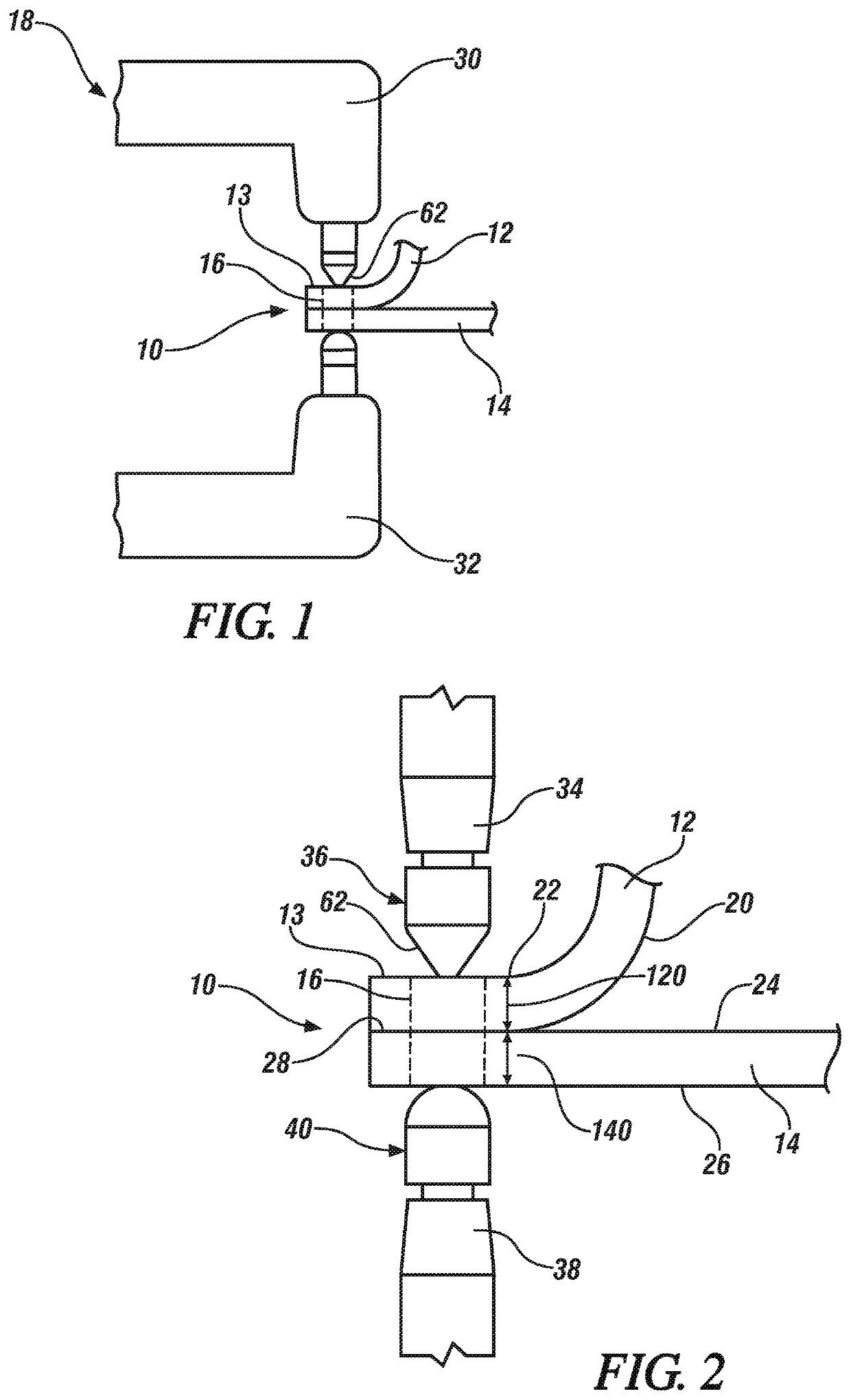
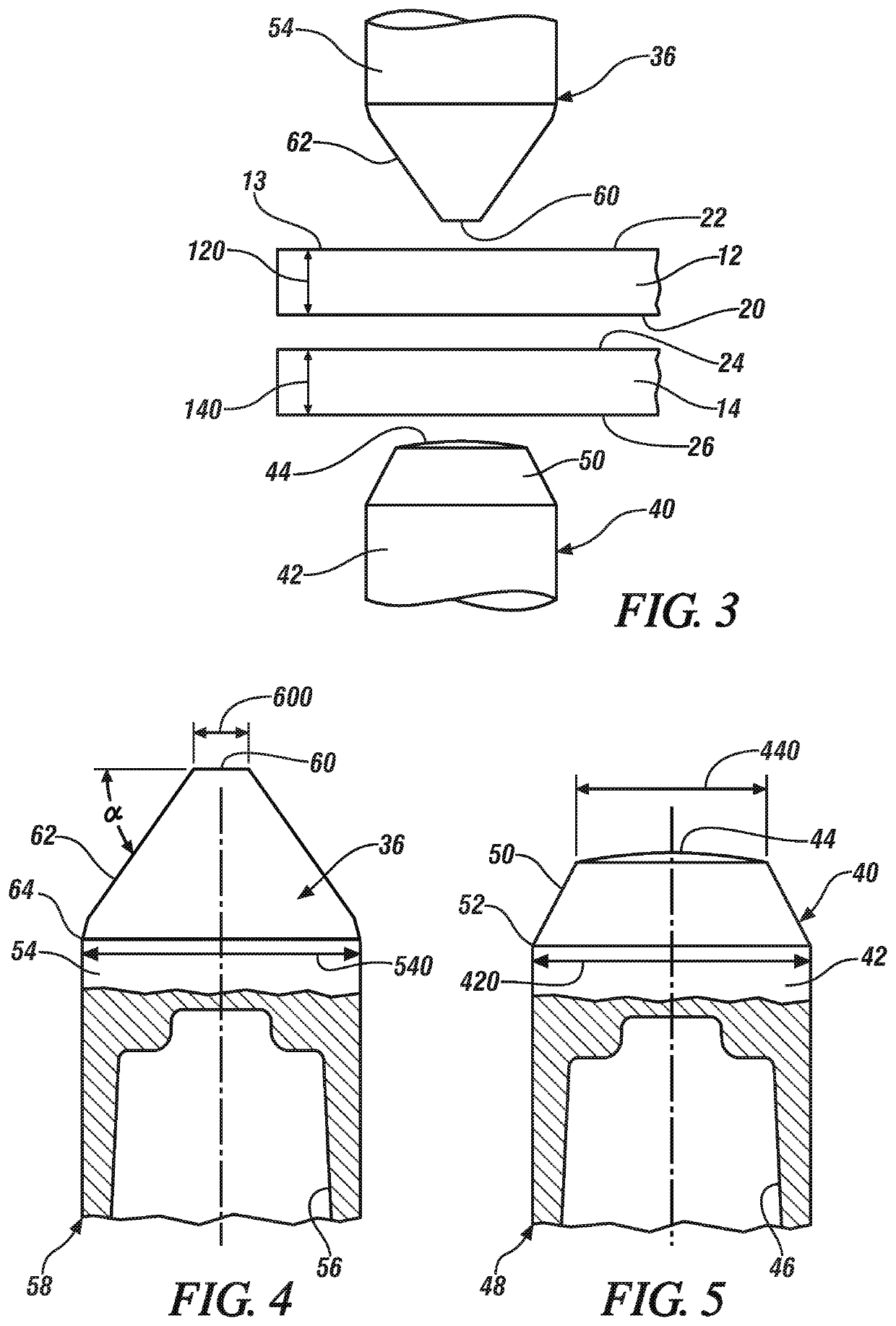
[0028]FIGS. 1-3 generally depict a workpiece stack-up 10 that includes a flanged steel workpiece 12 and an aluminum alloy workpiece 14 that are assembled in overlapping fashion for resistance spot welding at a predetermined weld site 16 by a welding gun 18. In this case, the steel workpiece 12 is characterized by a narrow flange portion 13 for contact with a weld electrode. The aluminum alloy workpiece 14 provides an ample surface area at the intended weld site. The practices of this disclosure may also be utilized when the stack-up includes a second aluminum alloy workpiece placed, side-to-side, against the outer surface 26 of the aluminum alloy workpiece 14, stacked against the narrow flange portion 13 of the steel workpiece 12. Also, the practices of this invention may be utilized when the stack-up includes a second steel alloy workpiece placed side-to-side against surface 20 of the steel workpiece 12. In this illustration, neither a second aluminum workpiece nor a second steel w...


PUM

PropertyMeasurementUnit
thicknessesaaaaaaaaaa
aspect ratioaaaaaaaaaa

Abstract

An electrical resistance spot welding electrode is disclosed for contact with a narrow or other selected spot weld region in a steel workpiece in a stack-up with an aluminum alloy workpiece for use in a spot welding method in which the weld nugget is carefully formed in the aluminum workpiece at the interface of the stack-up. The welding face of the welding electrode for contact with the steel workpiece is shaped with an aspect ratio greater than one, which fits against the contact surface of the steel workpiece, while the welding face for the aluminum-contacting weld electrode is circular (with an aspect ratio equal to one). The stack-up of workpieces may include a single steel workpiece facing two aluminum workpieces in a sandwich type stack-up or two steel workpieces facing a single aluminum workpiece with the outer steel workpiece having the narrow contact surface for the steel welding electrode.

Description

INTRODUCTION[0001]Resistance spot welding is a process used by a number of industries to join together two or more metal workpieces. The automotive industry, for example, often uses resistance spot welding to join together metal workpieces during the manufacture of vehicle structural frame members (e.g., body sides and cross-members) and vehicle closure members (e.g., vehicle doors, hoods, trunk lids, and lift gates), among others. A number of spot welds are often formed at various points around a peripheral edge of a stack-up of overlying metal workpieces, or some other bonding region, to ensure the part is structurally sound. While spot welding has typically been practiced to join together certain similarly composed metal workpieces—such as steel-to-steel and aluminum-to-aluminum—the desire to incorporate lighter weight materials into a vehicle body structure has generated interest in joining steel workpieces to aluminum workpieces by resistance spot welding. Such steel and alumin...

Claims


Application Information

Patent Timeline
Patent Type & Authority Patents(United States)
IPC IPC(8): B23K11/20B23K11/11B23K11/30B23K35/02B23K11/31B23K103/20B23K101/00
CPCB23K11/20B23K11/115B23K11/3009B23K35/0261B23K11/314B23K2101/006B23K2103/20B23K11/11B23K2103/18
Inventor HASELHUHN, AMBERLEE S.SIGLER, DAVID R.
Owner GM GLOBAL TECH OPERATIONS LLC
Why Eureka
Try Eureka