Optical soot particle sensor for motor vehicles

a soot particle and motor vehicle technology, applied in the field of soot particle sensor, can solve the problems of small soot particles, only having a small proportion of the total mass, and computation of numeric concentration, etc., to reduce simplify the activation and evaluation, and reduce the effect of the price of the entire sensor uni

Active Publication Date: 2021-07-27
ROBERT BOSCH GMBH
View PDF22 Cites 1 Cited by
  • Summary
  • Abstract
  • Description
  • Claims
  • Application Information

AI Technical Summary

Benefits of technology

[0009]The laser light of the CW laser is focused via the optical element (for example, a lens) on a very small spot. It is entirely possible that the laser is modulated, but a CW laser may be used. This enables the usage of cost-effective semiconductor laser elements (laser diodes), which reduces the price of the entire sensor unit and greatly simplifies the activation and evaluation. It may be ensured by the very small spot dimensions (for example, several μm) that at most one soot particle is always located in the spot, and the measured signal only originates from this one soot particle.
[0010]A single particle measurement is thus possible, which enables the extraction of pieces of information about the soot particles such as its size. This represents a clear advantage over other measuring methods for soot particle measurement. The present invention also advantageously permits a high measuring speed (at least 1 measurement per second in comparison to multiple minutes per measurement) and offers the option of a measurement of the particle count. The present invention thus permits both the determination of the mass concentration (mg / m3 or mg / km) and the numeric concentration (soot particles / m3 or soot particles / km) of the emitted soot particles.

Problems solved by technology

The computation of the numeric concentration (number of particles per m3 exhaust gas or per km driving distance) is only possible with great difficulty or is even impossible in the case of this sensor concept for manifold reasons.
It is to be noted that in particular the small soot particles, which only have a small proportion of the total mass due to their very small mass (m˜r3), are particularly hazardous.
This is because of their high “penetration depth” into the human body, which results from their small size.

Method used


Image

  • Optical soot particle sensor for motor vehicles
  • Optical soot particle sensor for motor vehicles
  • Optical soot particle sensor for motor vehicles

Examples


Embodiment Construction

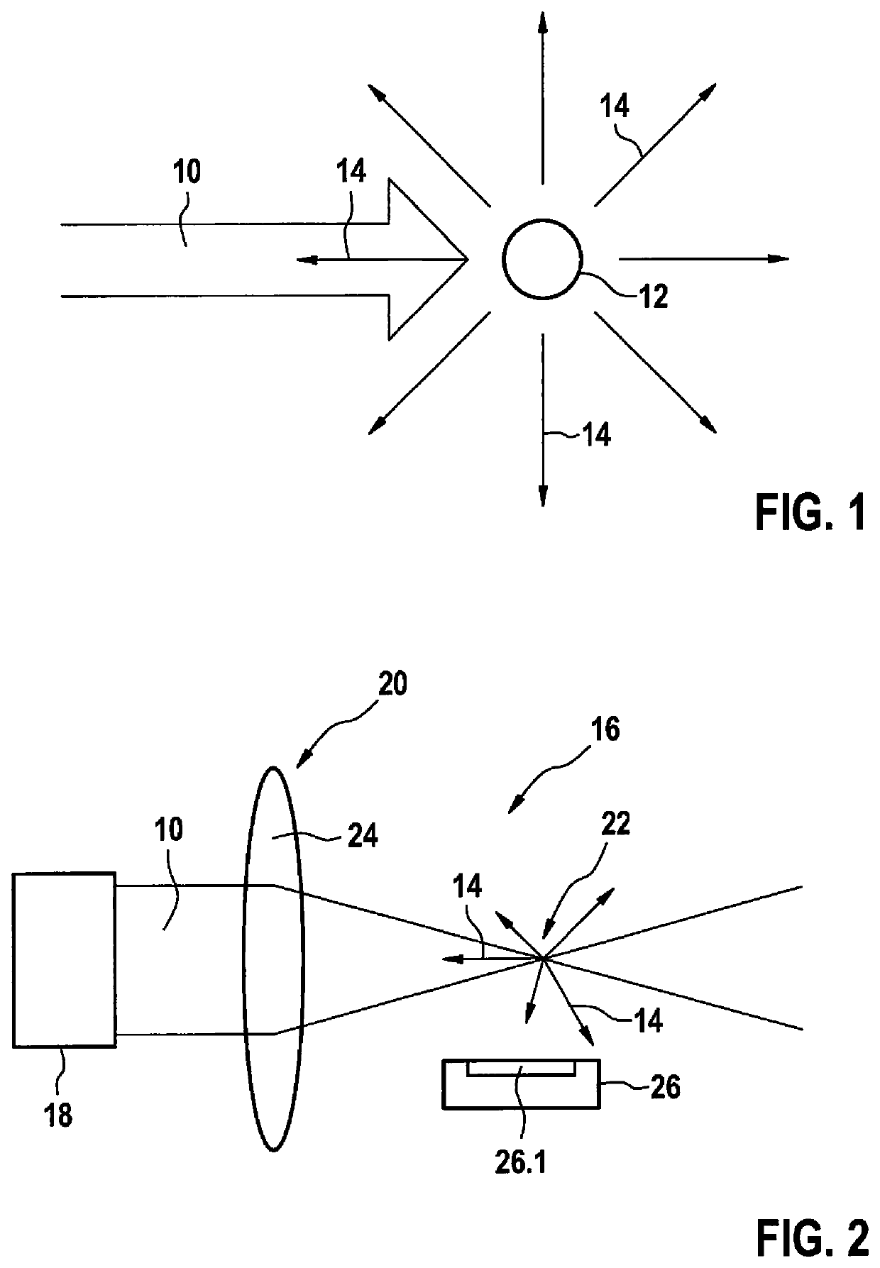
[0048]FIG. 1 illustrates the measuring principle based on laser-induced incandescence (LII). Laser light 10 of high intensity is incident on a soot particle 12. The intensity of laser light 10 is sufficiently high that the energy of laser light 10 absorbed by soot particle 12 heats soot particle 12 to several thousand degrees Celsius. As a consequence of the heating, soot particle 12 emits significant radiation 14, spontaneously and essentially without a preferred direction, in the form of temperature radiation, also referred to hereafter as LII light. A part of radiation 14 emitted in the form of temperature radiation is therefore also emitted opposite to the direction of incident laser light 10.

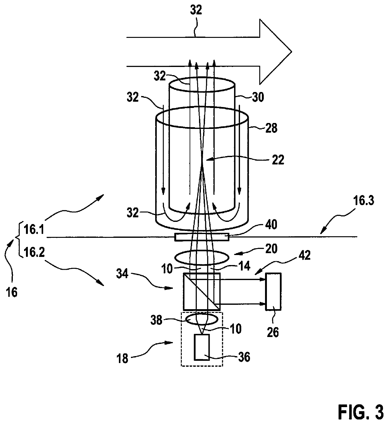
[0049]FIG. 2 schematically shows a basic structure of an exemplary embodiment of a soot particle sensor 16 according to the present invention. Soot particle sensor 16 includes a CW laser module 18 (CW: continuous wave) here, whose parallel laser light 10 is focused using at least one optica...


PUM

PropertyMeasurementUnit
wavelengthsaaaaaaaaaa

Abstract

A soot particle sensor includes a laser module including a laser and a detector configured for the detection of temperature radiation. The soot particle sensor provides that the laser is configured to generate laser light, and the soot particle sensor includes an optical element situated in the beam path of the laser of the laser module, which is configured to bundle laser light originating from the laser module in a spot, and the detector is situated in the soot particle sensor so that it detects the radiation originating from the spot.

Description

FIELD OF THE INVENTION[0001]The present invention relates to a soot particle sensor. Such a soot particle sensor includes a laser module having a laser and a detector configured for detecting temperature radiation.BACKGROUND INFORMATION[0002]Motor vehicles driven using modern diesel engines are equipped with diesel particle filters. The functionality of these particle filters has to be monitored using an onboard diagnostic apparatus / arrangement in accordance with legal regulations. For motor vehicles, for example, sensors including an electrical resistor, which are manufactured and sold by the applicant, are used. The operating principle of these known sensors is based on the formation of conductive soot paths between two interdigital electrodes. In the sensors, the rise time of the current after application of a voltage is a measure of the soot concentration. The mass concentration (mg / m3 exhaust gas or mg / km driving distance) is measured. The computation of the numeric concentrati...

Claims


Application Information

Patent Timeline
Patent Type & Authority Patents(United States)
IPC IPC(8): G01J3/30G01N21/71F01N11/00
CPCG01N21/718F01N11/002F01N2900/1606G01N21/71G01N2021/8557G01N2015/0046G01N15/0205G01N2015/1486G01N2015/1493G01N15/1459G01N2015/1075
Inventor RUSANOV, RADOSLAVKRAEMMER, CHRISTOPH DANIELKRAYL, OLIVER
Owner ROBERT BOSCH GMBH
Why Eureka
Try Eureka