Heat dissipation sheet

a technology of heat dissipation sheet and carbon fiber, which is applied in the direction of solid-state devices, basic electric elements, chemistry apparatus and processes, etc., can solve the problems of insufficient thermal conductivity in a thickness direction, insufficient flexibility, and insufficient flexibility, etc., to achieve excellent thermal conductivity, excellent thermal conductivity, and high thermal conductivity

Active Publication Date: 2021-08-31
TEIJIN LTD
View PDF12 Cites 0 Cited by
  • Summary
  • Abstract
  • Description
  • Claims
  • Application Information

AI Technical Summary

Benefits of technology

[0038]According to the present invention, a heat dissipation sheet having high thermal conductivity as compared with a heat dissipation sheet known in the prior art is provided. Also, a heat dissipation sheet having particularly excellent thermal conductivity in one specific direction of the heat dissipation sheet is provided. Further, a heat dissipation sheet having excellent thermal conductivity not only in an in-plane direction of the heat dissipation sheet but also in a thickness direction is provided.
[0039]Such a heat dissipation sheet is formed extremely thin and has high thermal conductivity as compared with conventional products. Therefore, it is promising for applications that have a large calorific value and limited space (e.g., smartphone, heater, copier roller, LED, automobile, CPU).

Problems solved by technology

However, it could not be said that this pitch-based carbon fiber filler had sufficient properties as a heat dissipation sheet because of its large fiber diameter.
Therefore, the alumina is dispersed in the carbon fiber, thus thermal resistance is large, and it cannot be said that thermal conductivity in a thickness direction is sufficient.
Also, since the fiber diameter is large, it cannot be said that flexibility is sufficiently excellent.

Method used


Image

  • Heat dissipation sheet
  • Heat dissipation sheet

Examples


manufacturing example 1

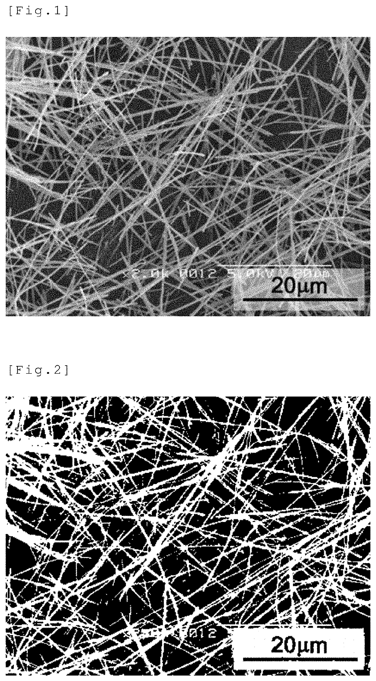
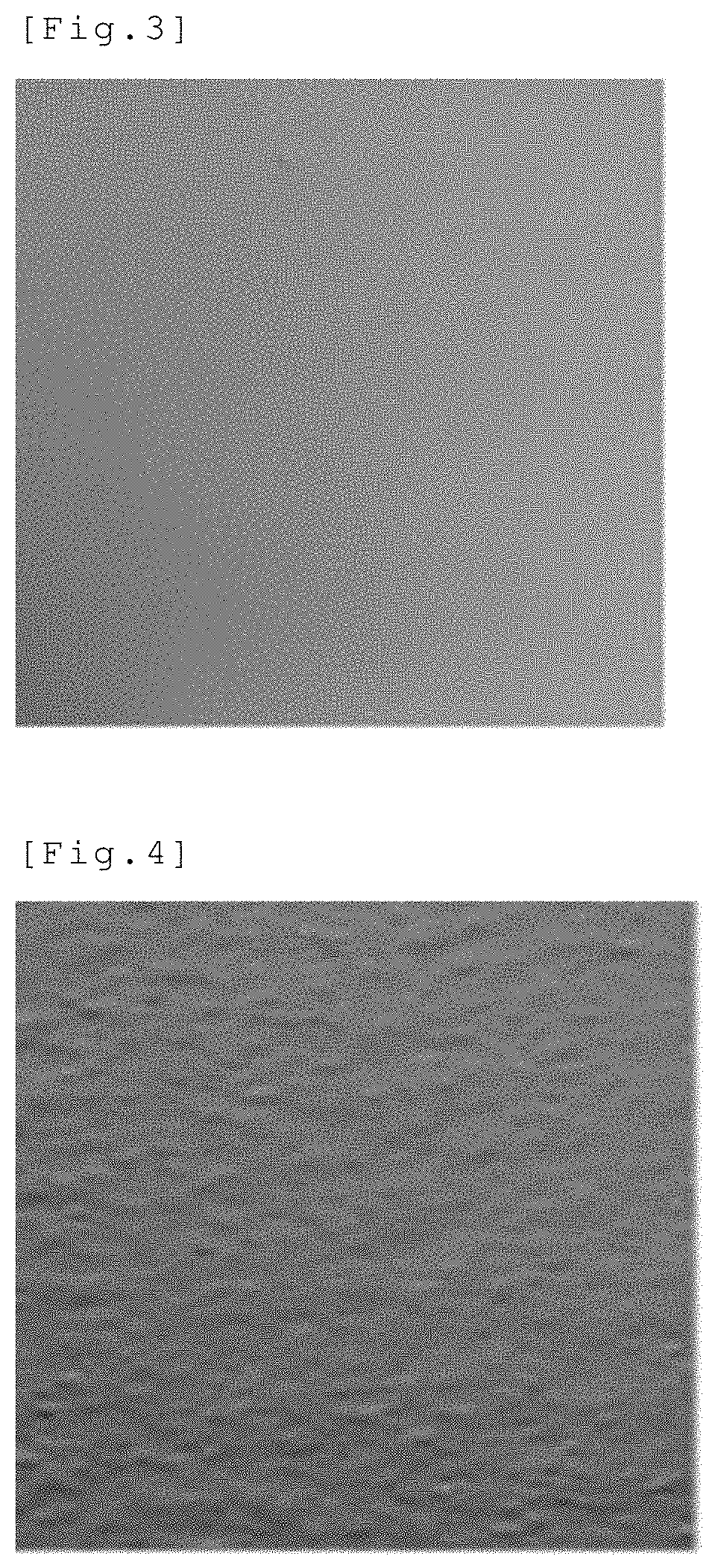
Manufacturing of Fibrous Carbon

[0177]90 parts by mass of high-density polyethylene (manufactured by Prime Polymer Co., Ltd., HI-ZEX 5000 SR, melt viscosity: 14 Pa·s at 350° C. and 600 s−1, MFR=0.37 g / 10 min) as a thermoplastic resin and 10 parts by mass of Mesophase Pitch AR-MPH (manufactured by Mitsubishi Gas Chemical Company, Inc.) as a mesophase pitch were melt-kneaded in a co-rotating twin-screw extruder (“TEM-26SS” manufactured by TOSHIBA MACHINE CO., LTD., at a barrel temperature of 310° C. under a nitrogen gas stream) to prepare a mesophase pitch composition. The dispersion diameter of the mesophase pitch in the thermoplastic resin was 0.05 to 2 μm. Also, this mesophase pitch composition was held at 300° C. for 10 minutes, but aggregation of the mesophase pitch was not observed and the dispersion diameter was 0.05 to 2 μm.

[0178]Then, this mesophase pitch composition was molded into a 60 μm-thick planar body using a rectangular nozzle with a slit width of 0.2 mm, a slit length...

example 1

[0183]Using N-methyl-2-pyrrolidone as a solvent, polyvinylidene fluoride (manufactured by Kureha Corporation) was dissolved in this solvent so that the concentration of the binder was 10% by mass. Then, the fibrous carbon (Manufacturing Example 1) was added to this solution and kneaded to obtain a slurry. The blending amount of the fibrous carbon was set to 50% by mass with respect to the total amount of the polymer and the fibrous carbon. This slurry was poured onto a polytetrafluoroethylene (PTFE) film and molded to a thickness of 0.3 mm by a doctor blade method at a casting speed of 0.5 cm / min. After heat treatment at 80° C. for 1 hour, heat treatment was further performed at 150° C. for 2 hours to obtain a heat dissipation sheet with a length of 200 cm, a width of 150 cm, and a thickness of 0.1 mm. This heat dissipation sheet had a smooth and supple surface. Values of the thermal conductivity in the in-plane direction (MD direction) and thickness direction of the heat dissipatio...

example 2

[0184]The same procedure as in Example 1 was carried out except that the blending amount of the fibrous carbon was 25% by mass to obtain a heat dissipation sheet. Values of the thermal conductivity in the in-plane direction (MD direction) and thickness direction of the heat dissipation sheet are shown in Table 1.


PUM

PropertyMeasurementUnit
volume resistivityaaaaaaaaaa
packing densityaaaaaaaaaa
thicknessaaaaaaaaaa

Abstract

The present invention provides a heat dissipation sheet comprising fibrous carbon and a polymer, wherein: the fibrous carbon has an average effective fiber length of 5-120 μm, an average fiber diameter of 200-900 nm, and an average aspect ratio of 30-10,000; and the heat dissipation sheet has a fibrous carbon content of 5-85% by mass with respect to the total amount of the fibrous carbon and the polymer.

Description

CROSS REFERENCE TO RELATED APPLICATIONS[0001]This application is a National Stage of International Application No. PCT / JP2017 / 035119 filed Sep. 28, 2017, claiming priority based on Japanese Patent Application No. 2016-189720 filed Sep. 28, 2016 and Japanese Patent Application No. 2016-225832 filed Nov. 21, 2016.TECHNICAL FIELD[0002]The present invention relates to a heat dissipation sheet. More specifically, the present invention relates to a heat dissipation sheet containing fibrous carbon and having excellent thermal conductivity.BACKGROUND ART[0003]Carbon nanomaterials, especially, fibrous carbon with an average fiber diameter of 1 μm or less, have excellent properties such as high crystallinity, high electroconductivity, high strength, a high elastic modulus and light weight, and are therefore used as nanofillers of high-performance composite materials. The application thereof is not limited to reinforcing nanofillers intended for improvement of mechanical strength, and by makin...

Claims


Application Information

Patent Timeline
Patent Type & Authority Patents(United States)
IPC IPC(8): C09K5/14C08K3/04C08J5/04C08K3/22C08K3/36C08K7/06C08K7/24H05K7/20H01L23/373C08J5/18C08L101/00
CPCC09K5/14C08J5/042C08J5/18C08K3/04C08K3/041C08K3/22C08K3/36C08K7/06C08K7/24C08L101/00H01L23/373H01L23/3733H01L23/3737H05K7/20C08J2377/00C08K2003/2227C08K2201/001C08K2201/003C08K2201/004C08K2201/005C08K2201/011C08K2201/016C08K3/013C08L77/00
Inventor CHA, GUEMJUKOMURA, SHINYADAIDO, TAKAHIRO
Owner TEIJIN LTD
Why Eureka
Try Eureka