Method for detecting and converting infrared electromagnetic radiation

Active Publication Date: 2022-01-18
SENORICS GMBH
View PDF7 Cites 0 Cited by
  • Summary
  • Abstract
  • Description
  • Claims
  • Application Information

AI Technical Summary

Benefits of technology

[0127]It can be provided that at least one electrode is formed in a number of pieces (i.e. as an array). Due to the electrode segments arranged in an array-like manner, there are advantageously a plurality of measurement ranges present in the optoelectronic component which are each read out separately by a read-out unit. This enables on the one hand a spatial resolution (for example for use in a camera with IR detector) of an irradiating electromagnetic signal that is to be d

Problems solved by technology

Based on the active medium used, a further subdivision can be made into the following four groups:a) The inorganic-based IR detectors are mostly based on the use of rare earths, for example indium or gallium, wherein the production thereof is technically demanding and therefore energy-intensive and in particular cost-intensive, which is disadvantageous.
Nevertheless, it is disadvantageous that the maximum external quantum efficiency of these IR detectors under short-circuit conditions is limited to 13.5% (at 1400 nm).e) Carbon-based IR detectors in which in particular carbon nanotubes or graphene monolayers are used have much lower maximum external quantum efficiencies of 2.3% or 2% under short-circuit conditions and at the same time allow absorption merely over a wide frequency band of from 400 nm to 1600 nm, so that the optoelectronic component is not selectively sensitive for IR radiation (Gong et al., ACS Applied Materials &Interfaces 2015, 150330161533004. doi:10.1021/acsami.5b01536 and Furchi et al., Nano Letters 2012, 12(6), 2773-2777).2. IR detectors which are based on the absorption of the direct interchromophoric charge transfer state are also known and are subdivided in accordance with the active medium used:a) Bednorz et al.
What is furthermore disadvantageous is that IR detectors of this kind are mechanically inflexible and their production requires rare earths, such as indium or gallium, which significantly increases the production cost.b) The absorption of the direct interchromophor

Method used


Image

  • Method for detecting and converting infrared electromagnetic radiation
  • Method for detecting and converting infrared electromagnetic radiation
  • Method for detecting and converting infrared electromagnetic radiation

Examples


Embodiment Construction

[0155]The above-mentioned embodiments according to the invention are suitable for achieving the object. Combinations of the disclosed embodiments are also suitable for achieving the object. Preferred developments of the invention will emerge from the combinations of the claims or individual features thereof.

BRIEF DESCRIPTION OF THE DRAWING FIGURES

[0156]The invention will be explained in greater detail hereinafter on the basis of some practical examples and the associated figures. The practical examples are intended to describe the invention, although the invention is not limited to the practical examples.

Here:

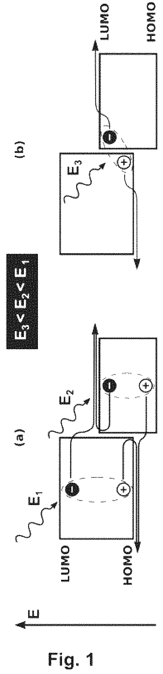
[0157]FIG. 1 shows an illustration of various absorption mechanisms within the scope of organic semiconductors and subsequent extraction of the charge carriers. The left-hand illustration (a) shows the conventional singlet absorption of the individual materials. The right-hand illustration (b) shows the absorption of the direct interchromophoric charge transfer state as used in...


PUM


Abstract

A method for detecting infrared electromagnetic radiation and for converting same into an electrical signal, an optoelectronic component, in particular an organic infrared detector for (near) infrared detection, and use thereof for detecting an electromagnetic signal in the wavelength range of 780 nm to 10 μm, are provided.

Description

CROSS REFERENCE TO RELATED APPLICATIONS[0001]This application is the National Phase filing under 35 U.S.C. § 371 of International Application No. PCT / EP2016 / 069256, filed on Aug. 12, 2016, and published on Feb. 23, 2017, as WO 2017 / 029223 A1, and claims priority to German Application No. 102015215581.1, filed on Aug. 14, 2015. The contents of each of the prior applications are hereby incorporated by reference herein in their entirety.FIELD OF THE INVENTION[0002]The present invention relates to a method for detecting infrared electromagnetic radiation and for converting same into an electrical signal, an optoelectronic component, in particular an organic infrared detector for (near) infrared detection, and use thereof for detecting an electromagnetic signal in the wavelength range of 780 nm to 10 μm.BACKGROUND ART[0003]Photosensitive, optoelectronic components convert electromagnetic ambient radiation into electricity. The component class comprises solar cells and detectors. Solar ce...

Claims


Application Information

Patent Timeline
IPC IPC(8): H01L31/0232H01L31/0256H01L51/44H01L51/42H01L27/30H01L31/054H01L31/18B82Y20/00
CPCH01L31/02327H01L27/307H01L31/0256H01L31/0547H01L31/18H01L51/447B82Y20/00H01L51/4253H01L2031/0344Y02E10/52Y02E10/549H10K39/32H10K30/87H10K39/30H10K30/30
Inventor SIEGMUND, BERNHARDVANDEWAL, KOENMISCHOK, ANDREASBENDUHN, JOHANNESSPOLTORE, DONATOKÖRNER, CHRISTIANLEO, KARL
Owner SENORICS GMBH
Why Eureka
Try Eureka