Crystal oscillator and startup method for a crystal oscillator

a crystal oscillator and startup method technology, applied in the field of crystal oscillators, can solve problems such as significant electric power consumption

Active Publication Date: 2022-02-08
THE SWATCH GRP RES & DEVELONMENT LTD
View PDF3 Cites 0 Cited by
  • Summary
  • Abstract
  • Description
  • Claims
  • Application Information

AI Technical Summary

Benefits of technology

[0010]In effect, the switch is opened thus providing regular charging and discharging of first and second capacitors. When switched into the driving mode the conductivity between the first terminal and the second terminal of the switch is increased. The first and second conductors are then effectively decoupled from a controller or startup controller and power consumption can be significantly reduced. When switched in the driving mode there is no longer any need to load and to unload the first and second capacitors. Rather, the capacitors now operate and behave as so-called coupling capacitors.
[0012]The switch is typically connected between first terminals of first and second capacitors. In this way the electrical conductivity between the first terminals of first and second capacitors can be modified during and / or for the startup procedure of the crystal oscillator. When in the startup mode the switch is typically open and there is no connection between the first terminals of first and second capacitors. When switching the crystal oscillator into the driving mode the first terminals of the first and second capacitors can be effectively connected, thereby reducing the impedance to ground as well as to effectively decoupled the first and second capacitors from an injection source, e.g. provided by a startup controller.
[0021]Typically, first and second phase signals are derived and / or are obtained from a common source, namely from the phase output of the startup controller. In this way a well-defined phase shift between first and second phase signals can be obtained and maintained.
[0026]By setting the startup control signal provided at the startup control output to a logical zero the phase injection of the first and second capacitors by the startup controller can be effectively switched off.
[0027]According to a further example one of the first input terminals of the first and second logic gate is coupled to the phase output by an inverter. Assumed that the phase output of the startup controller provides a periodic oscillating signal the output of the first logic gates can be effectively inverted or phase shifted by 180° compared to the output of the second logic gate. In this way the required phase shifting between first and second phase signals for charging or discharging first and second capacitors and / or for driving first and second buffer amplifiers can be provided.
[0028]According to another example the second input terminals of the first and second logic gates are connected to the third terminal of the switch via an inverter. In this way a concurrent operation of first and second logic gates compared to the switching behavior of the switch can be provided. In effect and by making use of an inverter between the third terminal of the switch and second input terminals of first and second logic gates the switch can be effectively turned on, thereby switching the crystal oscillator into the driving mode. Simultaneously or concurrent with the switching on of the switch the first and second logic gates can be effectively shut down and first and second phase signals for charging first and second capacitors will no longer be generated. This way electric power can be effectively saved.

Problems solved by technology

With such a conventional oscillator architecture there is a significant consumption of electric power caused by the frequent loading and unloading of the capacitors being tied to ground.

Method used


Image

  • Crystal oscillator and startup method for a crystal oscillator

Examples


Embodiment Construction

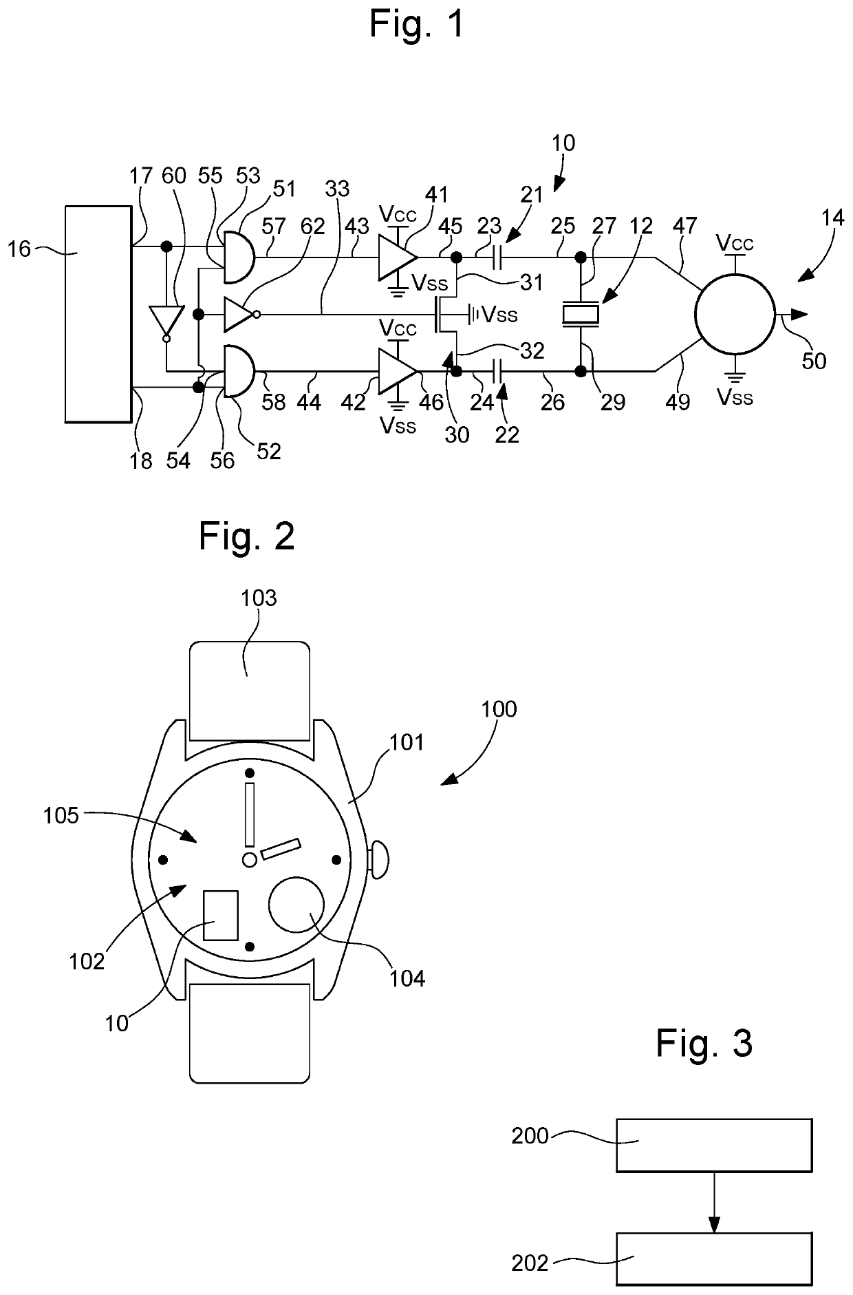
[0037]In FIG. 1 a block diagram of one implementation of the crystal oscillator 10 is described in greater detail. The crystal oscillator 10 comprises a crystal resonator 12. The crystal resonator 12 typically comprises a quartz crystal. The crystal oscillator 10 further comprises an electronic oscillator circuit 14 electrically connected to the crystal resonator 12. The crystal resonator 12 and the electronic oscillator circuit 14 are connected in parallel. The electronic oscillator circuit 14 comprises an output terminal 50 by way of which a well-defined and frequency stabilized clock signal synchronized to the resonance frequency of the crystal resonator 12 can be provided.

[0038]The crystal oscillator 10 further comprises first and second capacitors 21, 22. The first and second capacitors 21, 22 are connected to respective input and output terminals 47, 49 of the electronic oscillator circuit 14. In detail the first capacitor 21 comprises a second terminal 25 electrically connect...


PUM


Abstract

A crystal oscillator and a startup method for initiating operation of a crystal oscillator with a crystal resonator including a first terminal and a second terminal, an electronic oscillator circuit connected to the crystal resonator, a first capacitor including first and second terminals, the second connected to the first terminal of the crystal resonator, a second capacitor including first and second terminals, the second connected to the second terminal of the crystal resonator. A switch includes first, second and third terminals, wherein an electrical conductivity between the first terminal and the second terminal of the switch is controllable by a voltage at the third terminal, wherein the first terminal of the switch is connected to the first terminal of the first capacitor and wherein the second terminal of the switch is connected to the first terminal of the second capacitor.

Description

CROSS-REFERENCE TO RELATED APPLICATION[0001]This application claims priority to European Patent Application No. 20194779.2 filed on Sep. 7, 2020, the entire disclosure of which is hereby incorporated herein by reference.FIELD OF THE INVENTION[0002]The present disclosure relates to a crystal oscillator and to a portable electronic device comprising such a crystal oscillator. In another aspect, the disclosure relates to a method of initiating operation of a crystal oscillator.BACKGROUND OF THE INVENTION[0003]Crystal oscillators are widely known in the prior art. A crystal oscillator is an electronic oscillating circuit that uses the mechanical resonance of a vibrating crystal of piezoelectric material to create an electric signal with a precise frequency. This frequency is often used to keep track of time, as in quartz-controlled wristwatches in order to provide a stable clock signal for digital integrated circuits and / or to stabilize frequencies for radio transmitters and receivers.[...

Claims


Application Information

Patent Timeline
Patent Type & Authority Patents(United States)
IPC IPC(8): H03B5/32H03B5/06H03K3/012
CPCH03B5/32H03B5/06H03K3/012H03L3/00H03B5/364H03B2200/0094H03B2200/005
Inventor CASAGRANDE, ARNAUDAREND, JEAN-LUC
Owner THE SWATCH GRP RES & DEVELONMENT LTD
Why Eureka
Try Eureka