Process for combined production of ammonia and urea

a technology of ammonia and urea, which is applied in the direction of gas-gas reaction process, physical/chemical process catalyst, bulk chemical production, etc., can solve the problems of high energy consumption and operating costs, unsatisfactory conversion yield, and relatively high h.sub.2o/co.sub.2 molar ratio in such synthesis reactors

Inactive Publication Date: 2001-05-31
UREA CASALE SA
View PDF0 Cites 6 Cited by
  • Summary
  • Abstract
  • Description
  • Claims
  • Application Information

AI Technical Summary

Benefits of technology

[0033] Advantageously, thanks to the process according to the present invention, and in particular to the step of partial decomposition of the carbamate coming from the urea recovery section, it is possible to send to the carbamate synthesis section a water-rich solution, and to send at the same time to the urea synthesis reactor a flow comprising ammonia and substantially anhydrous carbon dioxide, which allows to reduce the H.sub.2O / CO.sub.2 molar ratio in such reactor increasing therefore the urea conversion yield.
[0069] Thanks to the aforementioned method of modernization that combines an existing ammonia plant and an existing urea plant, it is possible to obtain--in a simple and economical way--a high urea conversion yield and at the same time drastic reductions in operating costs and energy consumption.

Problems solved by technology

A first drawback of this process lies in that the high development of heat produced during carbamate production and the presence of inert gases (hydrogen and nitrogen) which reduce the partial pressure of ammonia and carbon dioxide makes it necessary to operate--in the urea synthesis reactor--at high pressures to keep reactants in a liquid phase, with ensuing high energy consumption and operating costs.
Moreover, because of the introduction in the urea synthesis reactor of a high amount of water--for instance in the form of carbamate in aqueous solution--to facilitate the absorption of carbon dioxide in the ammonia solution and the subsequent reaction into carbamate, the H.sub.2O / CO.sub.2 molar ratio in such synthesis reactor is relatively high and the conversion yield is unsatisfactory.
A further drawback lies in the structural and operating complexity of the urea synthesis reactor necessary for implementing the above described process, which must include a special unit for the separation of inert gases (hydrogen and nitrogen) from carbon dioxide and from ammonia in the vapour phase.
In addition, carbamate formation heat that is released during carbon dioxide absorption with the ammonia solution causes a strong evaporation of the latter, which involves the need of an additional recovery of ammonia at the outlet of the carbamate synthesis section, with ensuing problems of excessive dilution of the carbamate.
At the same time, as the urea conversion reactor lacks carbamate formation heat, the operating conditions in said reactor become more difficult.
Otherwise said, according to this process of the prior art, producing carbamate outside the urea synthesis reactor involves not only the loss of the related formation heat, but also requires an addition of water, which is in contrast with the subsequent dehydration to urea, and therefore does not allow to obtain satisfactory conversion yields.
In conclusion, the processes for combined production of ammonia and urea according to prior art, besides requiring very complex plants for their implementation, and involving high investment and operating costs, as well as high energy consumption, do not allow in any case to obtain a high urea conversion yield due to the excessive H.sub.2O / CO.sub.2 molar ratio present in the corresponding synthesis reactor.
Because of these drawbacks, the above processes have not found till now a concrete application, in spite of the increasingly felt requirement in the field.

Method used


Image

  • Process for combined production of ammonia and urea

Examples


Embodiment Construction

[0072] With the only aim of making the description of the present invention simpler, reference will be made to the connection ducts of the different plant parts, as well as to the same plant parts described in the following and represented in FIG. 1, conventional in themselves, only wherever it is strictly necessary.

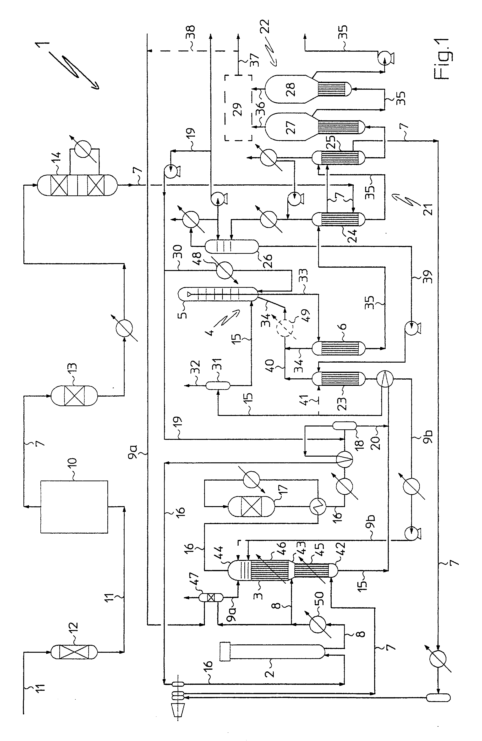
[0073] With reference to FIG. 1, there is generally indicated by 1 a plant for combined production of ammonia and urea according to the invention.

[0074] Advantageously, plant 1 comprises an ammonia synthesis reactor 2, a carbamate synthesis section 3, a urea synthesis section 4, a urea recovery section 21, and a carbamate decomposition section 23.

[0075] The urea synthesis section 4 comprises, serially arranged relatively to one another, a urea synthesis reactor 5 and a high pressure (about 180 bar a) stripper 6, for the partial decomposition of carbamate and the separation of the free ammonia in aqueous solution present in the reaction mixture coming from reactor 5.

[0076...


PUM

PropertyMeasurementUnit
pressureaaaaaaaaaa
pressureaaaaaaaaaa
pressureaaaaaaaaaa

Abstract

A process for the combined production of ammonia and urea of the type comprising an ammonia synthesis reactor (2), a urea synthesis reactor (5) and a urea recovery section (21) stands out for the fact of submitting at least a part of a flow comprising carbamate in aqueous solution coming from the urea recovery section (21) to a partial decomposition treatment, to obtain a flow comprising ammonia and carbon dioxide in vapor phase and a flow comprising diluted carbamate in aqueous solution, which is fed together with a gas flow comprising hydrogen, nitrogen and carbon dioxide, preferably obtained by hydrocarbons steam reforming, and a flow comprising ammonia coming from the ammonia synthesis reactor (2) to a carbamate synthesis section (3), where ammonia and carbon dioxide are caused to react, to obtain a flow comprising carbamate in aqueous solution and a gas flow comprising hydrogen and nitrogen. The flow comprising carbamate in aqueous solution is then sent to the urea synthesis reactor (5), while the gas flow comprising hydrogen and nitrogen is sent to the ammonia synthesis reactor (2).

Description

FIELD OF APPLICATION[0001] The present invention relates to a process for the combined production of ammonia and urea in a plant comprising an ammonia synthesis reactor, a urea synthesis reactor and a urea recovery section.[0002] In the following of the description and subsequent claims, with the term: "process for the combined production of ammonia and urea", it is intended to mean a single process that integrates the ammonia production process with the urea production process.[0003] In other words, according to this technology, urea is produced--at least in part--by causing ammonia obtained in a synthesis reactor to react with carbon dioxide contained in a synthesis raw gas flow comprising among other things hydrogen and nitrogen coming, for instance, from a reforming section. The synthesis raw gas flow, free from carbon dioxide, is thereafter sent to the ammonia synthesis reactor.[0004] Processes of this kind allow to eliminate, or in any case, to reduce to a remarkable extent, t...

Claims


Application Information

Patent Timeline
Patent Type & Authority Applications(United States)
IPC IPC(8): C07C273/04B01J12/02C01C1/04C07C273/10
CPCC01C1/0488C07C273/10Y02P20/582Y02P20/52
Inventor PAGANI, GIORGIOZARDI, UMBERTO
Owner UREA CASALE SA
Why Eureka
Try Eureka