Eureka AIR delivers breakthrough ideas for toughest innovation challenges, trusted by R&D personnel around the world.

Progressive start-up circuit for activating a charge pump

a start-up circuit and charge pump technology, applied in the direction of electric variable regulation, process and machine control, instruments, etc., can solve the problems of low power consumption, small size and cost, and the safety limitation of the amount of current that can be provided by the energy source, so as to enhance the service life of the battery and energy and amplitude on demand, and the effect of small siz

Inactive Publication Date: 2001-10-25
THE BOARD OF TRUSTEES OF THE UNIV OF ILLINOIS
View PDF0 Cites 70 Cited by
  • Summary
  • Abstract
  • Description
  • Claims
  • Application Information

AI Technical Summary

Benefits of technology

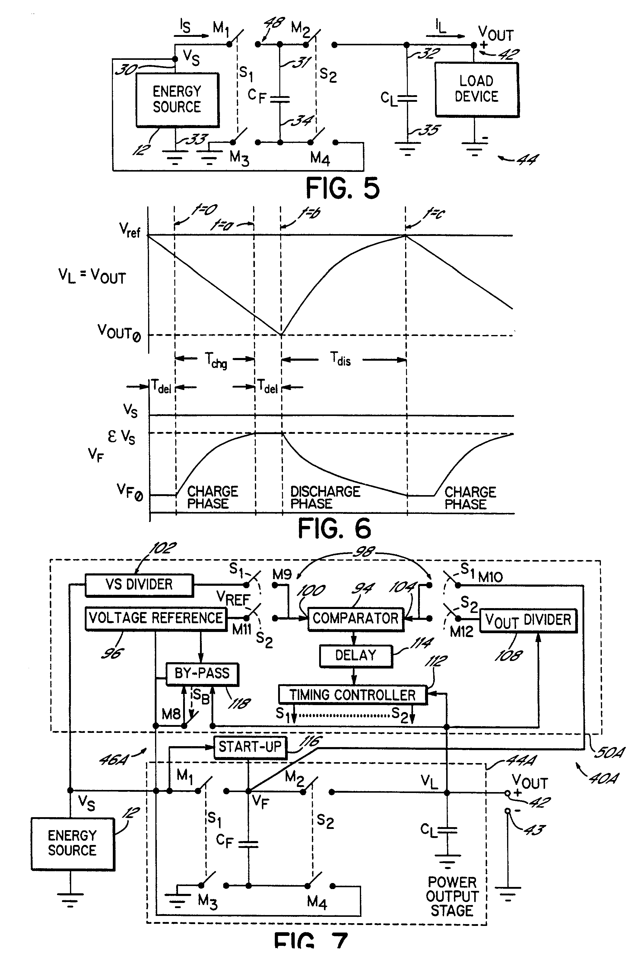
[0132] The series resistances encountered during the charge (R.sub.CHG) and discharge (R.sub.DIS) phases have the most significant effect on the maximum current capacity of the power output stage 44, as shown by the three operating point columns in Table 1. Although larger fly (C.sub.F) and load (C.sub.L) capacitors improve this capability, the amount of improvement is mitigated as their resistance increases. Increasing the capacitor values appears to have a greater proportional effect on reducing the output voltage ripple V.sub.RIP, rather than the current capacity.
[0181] Furthermore, the aspects of the invention related to dynamically adapting to the input voltage, especially with regard to a low input voltage, allow for applications wherein the input voltage is volatile or otherwise unsuitable for generally known power converters. For example, photovoltaic cells provide power in relation to the surface area and the amount of incident radiant energy. Consequently, devices using photovoltaic cells may often be inoperable due to insufficient light, may have to limit functionality to remain within the typical amount of available power, and / or have to increase the surface area devoted to photovoltaic cells. Thus, a power converter 40A may allow for smaller photovoltaic cells and use in a wider range of lighting conditions.

Problems solved by technology

The disadvantage of the short self-discharge time for electronic capacitors means that oscillator-based charge pumps 20 must operate at duty cycles that are between the rate in which the electronic capacitor can be charged and discharged and the rate at which the electronic capacitor will self-discharge.
Consequently, known oscillator-based charge pumps 20 cannot take advantage of ultra-capacitors and similar high storage devices that have self-discharge times measured in weeks or months.
Moreover, as will become apparent below, the power converter 40A may readily be implemented as an integrated circuit and thus be of small size and cost.
For example, the energy source may have a safety limitation on the amount of current that can be provided, perhaps for a certain duration.
This represents situations where the various protection measures may result in a situation where the power converter needs to be restarted.
In addition, the Schottky diode consumes power during normal operation of the oscillator-controlled power converter 20, thereby reducing efficiency.
This is due to the non-compensated nature of the comparator.
However, the current capability of this one small MOSFET is insufficient to charge the load capacitor C.sub.L.
For example, common-mode signals may be induced noise on the inputs.
Consequently, devices using photovoltaic cells may often be inoperable due to insufficient light, may have to limit functionality to remain within the typical amount of available power, and / or have to increase the surface area devoted to photovoltaic cells.

Method used


Image

  • Progressive start-up circuit for activating a charge pump
  • Progressive start-up circuit for activating a charge pump
  • Progressive start-up circuit for activating a charge pump

Examples


Embodiment Construction

POWER CONVERSION

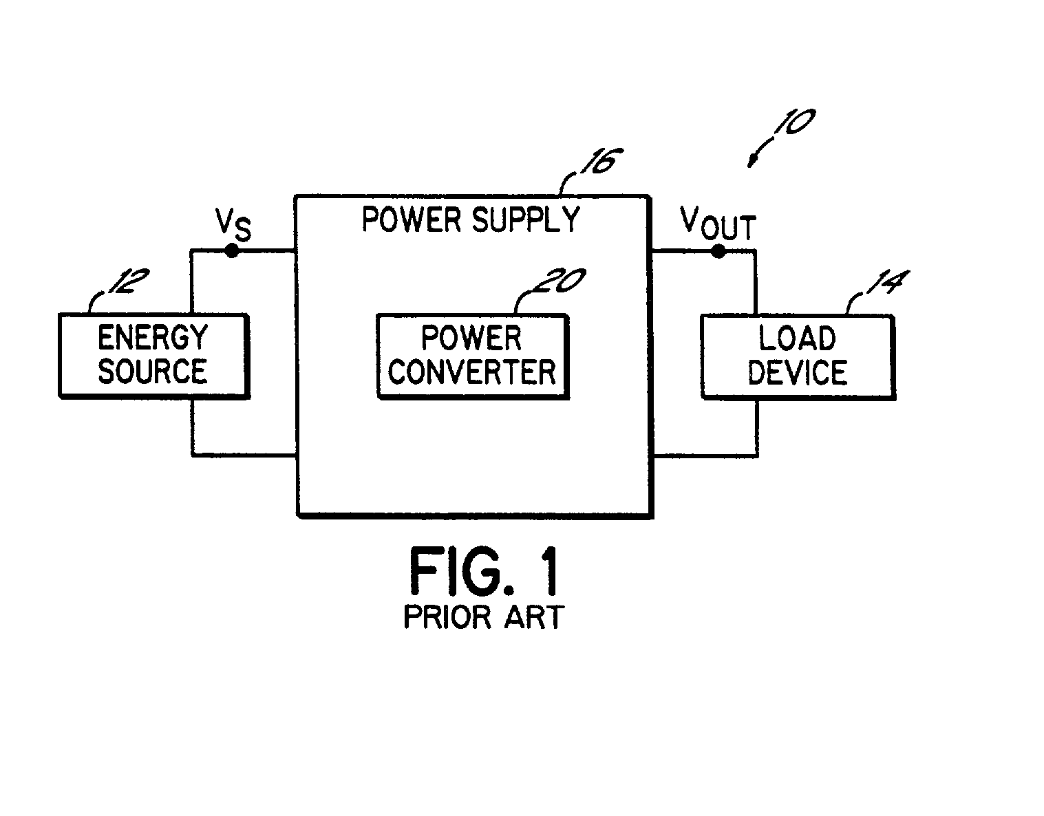
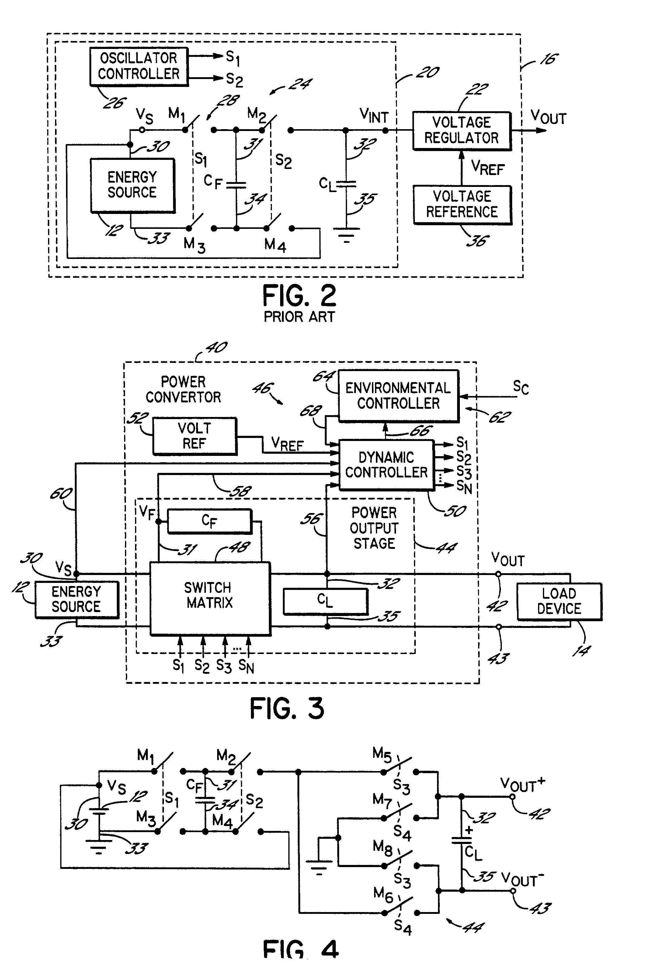
[0055] The operation and advantages of dynamic control of a charge pump in accordance with the principles of the invention is best understood by considering alternative power conversion techniques in existing power converters.

[0056] For example, a linear regulator is one type of existing power converter. Linear regulators have an efficiency that is directly proportional to the ratio of the input voltage V.sub.S to the output voltage V.sub.OUT. Thus, an input voltage V.sub.S that is twice the required output voltage V.sub.OUT would result in about half of the power from an energy source 12 being inefficiently consumed by the power converter 20. Due to the lower efficiency and resulting heat generation, linear regulators require a heat sink that often complicates or precludes integration into low profile packages such as those complying with the PCMCIA specification standard. Moreover, linear regulators generally require two discrete capacitors, further limiting reduct...


PUM


Abstract

A charge pump power converter efficiently provides electrical power by dynamically controlling a switch matrix of the charge pump. Instead of open-loop oscillator-based control, a dynamic controller provides power upon demand by sensing the output voltage and changing the operating frequency of the charge pump in response. Moreover, this closed-loop dynamic control intrinsically voltage regulates the output voltage of the charge pump power converter without the inefficient addition of a step-down voltage regulator, downstream of the power converter. In addition, this closed-loop dynamic control allows for maintaining a desired output voltage even with variations in the input voltage. Also, the dynamic control accommodates the advantages of using ultra-capacitors in the charge pump. The power converter is capable of operating with a sub-one volt input voltage incorporating low-threshold, low on-resistance power MOSFET switches in the switch matrix of the charge pump. A progressive start-up circuit further allows the power converter to start from a discharged state even with a sub-one volt input voltage.

Description

[0001] The present invention relates to DC / DC power supply controllers, and more particularly to regulated charge pump power converters for integrated power management systems.[0002] Advances in electronics technology have enabled the design and cost-effective fabrication of portable electronic devices. Thus, usage of portable electronic devices continues to increase both in the number of products available and the types of products. Examples of the broad spectrum of portable electronic devices include pagers, cellular telephones, music players, calculators, laptop computers, and personal digital assistants, as well as others.[0003] The electronics in a portable electronic device generally require direct current (DC) electrical power. Typically, one or more batteries are used as an energy source to provide this DC electrical power. Ideally, the energy source would be perfectly matched to the energy requirements of the portable electronic device. However, most often the voltage and c...

Claims


Application Information

Patent Timeline
Patent Type & Authority Applications(United States)
IPC IPC(8): H02J7/00H02M3/07H02M3/158
CPCH02J7/0065H02M3/07H02M3/1588Y02B40/90H04R2225/31H04R2225/33Y02B70/1466H02M2003/072H02J2207/20Y02B70/10H02M3/072Y02B40/00
Inventor NEBRIGIC, DRAGAN DANILO
Owner THE BOARD OF TRUSTEES OF THE UNIV OF ILLINOIS
Why Eureka
Eureka Blog
Learn More