

Method of cleaning a film deposition apparatus, method of dry etching a film deposition apparatus, and an article production method including a process based on the cleaning or dry etching method
a film deposition and cleaning technology, applied in the direction of lighting and heating apparatus, cleaning using liquids, instruments, etc., can solve the problems of film quality degradation, critical charging process, and film to have defects
- Summary
- Abstract
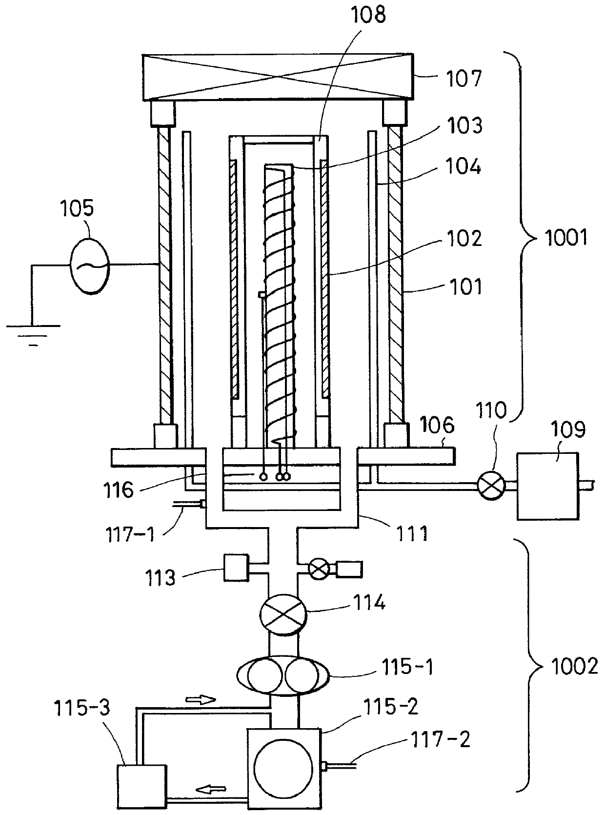
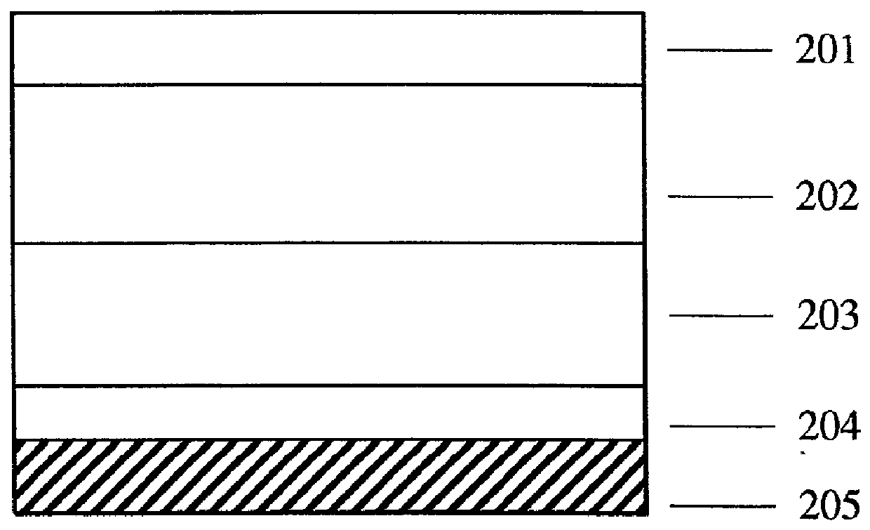
- Description
- Claims
- Application Information
AI Technical Summary
Benefits of technology
Problems solved by technology
Method used
Image

Examples
example 2
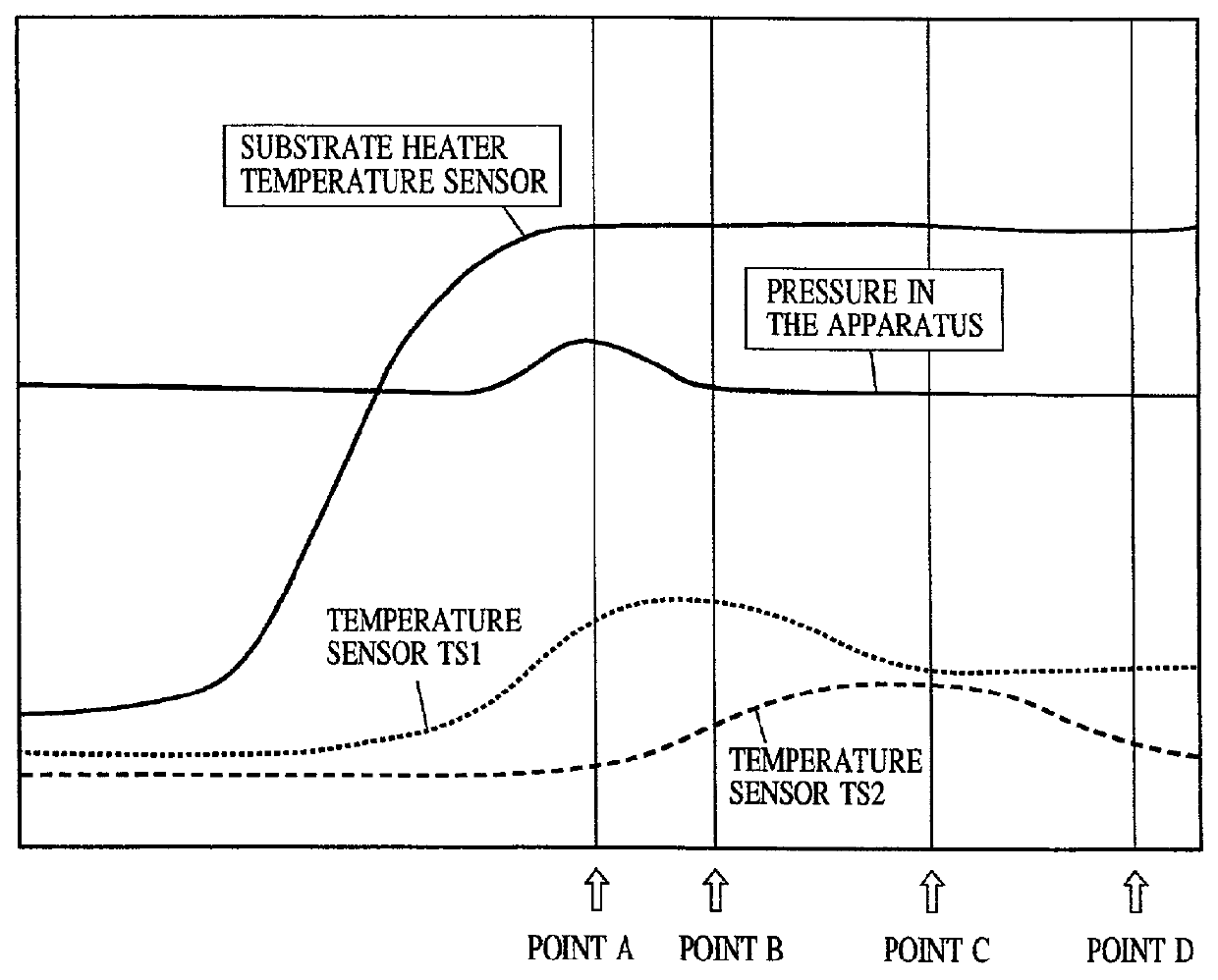
[0136] In Example, 2 the cleaning process was performed in a manner similar to Example 1 except that the cleaning process was completed at the point D, thereby producing electrophotographic photosensitive drums. The evaluation was performed in a similar manner to Example 1, and the results are shown in Table 3.
example 3
[0137] In Example 3, electrophotographic photosensitive drums were produced in a similar manner to Example 1 except that the concentration of the source gas was changed such that the concentration was different as between the cleaning steps before and after stopping the source gas and the high-frequency power, as shown in Table 4. The evaluation was performed in a similar manner to Example 1.
[0138] The cost required for the cleaning was also evaluated (in percentage) relative to the cost for the Comparative Example 1.
[0139] The results are shown in Table 5. Note that the timing of stopping the source gas and the high-frequency power was selected in a manner similar to Example 1.
4 TABLE 4 Concentration Processing Before Concentration Pressure (Pa) Stopping After Stopping Power 100 35% 25% 1800 W
[0140]
5 TABLE 5 Defects External Scattered Appear- Along Line Cleaning Cleaning ance Line Defects Time Cost Quality Example 3 .circle-w / dot. .circle-w / dot. .circle-w / dot. 98% 90% .circle-w / dot...
example 4
[0142] In Example 4, the cleaning process was performed and electrophotographic photosensitive drums were produced in a manner similar to Example 1 except that the internal pressure was changed as shown in Table 6, and the supplying of the source gas and the high-frequency power was stopped at points 2 and 4. In addition to a similar evaluation to Example 1, defects in the films due to abnormal growth were evaluated. The cost required for the cleaning was also evaluated (in percentage) relative to the cost for the Comparative Example 1. The results are shown in Table 7.
Evaluation of Defects in the films
[0143] The surfaces of the obtained electrophotographic photosensitive drums were observed via an optical microscope, and the number and the size of defects in the films due to abnormal growth were evaluated. In Table 7, the evaluation results are represented as follows:
[0144] .circle-w / dot.: The defect density was very low, and a excellent result was obtained.
[0145] .largecircle.: Al...
PUM
| Property | Measurement | Unit |
|---|---|---|
| Temperature | aaaaa | aaaaa |
| Temperature | aaaaa | aaaaa |
| Fraction | aaaaa | aaaaa |
Abstract
Description
Claims
Application Information