Manufacturing method of liquid crystal display device

a liquid crystal display and manufacturing method technology, applied in static indicating devices, instruments, cameras, etc., can solve the problems of bubbles in the inside of stored ink, the inability to manufacture throughput of color filter substrates and eventually the manufacturing throughput, and the inability to meet the requirements of the product quality control system

Inactive Publication Date: 2002-05-09
PANASONIC LIQUID CRYSTAL DISPLAY CO LTD +1
View PDF0 Cites 44 Cited by
  • Summary
  • Abstract
  • Description
  • Claims
  • Application Information

AI Technical Summary

Benefits of technology

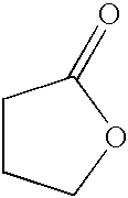
[0094] Further, the fact that, for the dyed medium such as acrylic resin, gelatin resin or the like which locally includes portions exhibiting hydrophilic property such as ester linkage, peptide linkage or the like in the molecules (macro-molecules), N-methyl-2-pyrrolidone or .gamma.-butyrolactone which is used as the dyeing-promoter agent includes peptide linkage and ester linkage in the inside of the molecule also increases the affinity between the dyed medium and the dyeing-promoter agent so that the permeation of the dye into the inside of the dyed media is accelerated. For example, even when four-membered ring, six-membered ring or seven-membered ring having ester linkage or peptide linkage (caprolactam C.sub.6H.sub.11NO, for example) is used in place of N-methyl-2-pyrrolidone or .gamma.-butyrolactone having the five-membered ring, the advantageous effects intended by the present invention can be obtained. Further, with respect to compounds having ester linkage or peptide linkage, to compare the molecular structures of these compounds, it is preferable to use substance which has side chains longer than the straight chain structure as the dyeing-promoter agent.
[0095] It is further preferable to use substance which has the ring structure as the dyeing-promoter agent.
[0096] Accordingly, on the assumption that the molecules of the dyeing-promoter agent are coordinated in the dye molecules in the coloring step of the color filters FIL, it is recommendable to use the compound having the molecular structure which is expanded in two dimensions compared to straight chain molecules as the dyeing-promoter agent. Here, the compounds which are used as the above-mentioned volatility-adjusting agent or the dyeing-promoter agent may be suitably transformed into other compounds depending on the kind of solvent into which the dye is dispersed. When the solvent is low alcohol or aldehyde, elements which constitute the ester linkage or the peptide linkage of the dyeing-promoter agent may be modified by the alkyl group. When the dyeing-promoter agent or the dyed medium includes the peptide linkage or ester linkage, the material exhibits characteristic peaks in the nuclear magnetic resonance spectrum and the infra red spectrum. With respect to the compositions of the dye, the volatility-adjusting agent, the dyeing-promoter agent and the solvent in the ink, respective weight percent values of respective materials can be specified based on the respective peak areas thereof in view of the difference of retention times of the peaks appearing in the spectra using a gas chromatography analyzer. Further, the ink according to the present invention may generate colloid when the ink is dropped into the phosphoric solvent (oil or the like).
[0097] As other criteria for selecting compounds which can be used as the dyeing promoter agent, it is preferable to focus on a point that the boiling point (corresponding to the volatility) of the dyeing-promoter agent is higher than that of the volatility-adjusting member and is higher than that of the solvent or a point that the viscosity of the dyeing-promoter agent is lower than that of the volatility-adjusting agent.
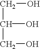
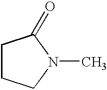
[0098] In an example which combines glycerin as the volatility-adjusting agent and N-methyl-2-pirrolidone as the dyeing-promoter agent, the boiling point of the former is 290.degree. C. and the boiling point of the latter is 202.degree. C. Further, with respect to the viscosity, a capillary is prepared by processing a glass tube, given quantities of respective liquids are filled in the capillary under the same environment (conditions such as temperature, humidity, atmospheric pressure or the like at the time of an experiment being set equal), and the magnitude of the viscosity was confirmed by measuring the time necessary for respective liquids to pass through the capillary. The volatility-adjusting agent which composes the ink according to the present invention is required to perform the function of suppressing the drying of ink within a period from a point of time that the ink is adhered to the surface of the dyed media to the point of time that the dye contained in the ink permeates into the inside of the dyed media to some extent. Further, the volatility-adjusting agent which composes the ink according to the present invention is required to perform the function of preventing the scattering of the ink in the process for ejecting the ink toward the surface of the dyed medium from the nozzle of the ink supply device. To take these request into consideration, it is requested that the boiling point of the volatility-adjusting agent is elevated above a given level with respect to the former request and it is requested that the viscosity of the volatility-adjusting agent is increased above a given level with respect to the latter request. However, these limitations may be alleviated depending on the improvement of the permeation characteristics of the dye into the inside of the dyed media due to the dyeing-promoter agent and the enhancement of the nozzle shape of the ink supply device.
[0099] That is, even when the combination of respective reagents used as the volatility-adjusting agent and the dyeing-promoter agent does not satisfy either one or both of these conditions, there still exists a possibility that an advantageous effects intended by the present invention can be obtained.

Problems solved by technology

As described above, the coloring resist method has to repeat the photolithography process for respective colors and hence, there exists a limitation with respect to the manufacturing throughput of the color filter substrates and eventually the manufacturing throughput of liquid crystal display devices for the color image display using such a method.
Further, in the color resist method, the resist in which the pigment of a given color is dispersed flows into or is scattered into a pixel region which is disposed close to or adjacent to a pixel region in which the color filter using such a resist is formed (the pixel region in which the another color filter made of the resist in which pigment having color different from the given color is dispersed) so that there is a possibility that an undesirable kind of pigment for another color filter may be mixed into another color filter.
However, when the ink chamber CHM is heated by the heater element HTR, bubbles are generated in the inside of the stored ink and the bubbles become large gradually.
However, on the other hand, the ink supply method which adopts the thermal jet method has a drawback that the formation of bubbles in the inside of the ink chamber CHM determines the ink supply conditions to the color filter substrate so that the proper control is difficult.
However, in the reality, even with the above-mentioned improvement of the ink composition, there still remains a drawback that the difference is generated in the concentration of color among dyed media which are colored in given colors (corresponding to pixels or a group of pixels of the liquid crystal display device).
That is, even when the physical properties of the ink (viscosity, surface tension, contact angle to the dyed media and the like) are optimized, the levels of the coloring concentrations of the dyed media with the dyes (this parameter being called "dyeing performance") become non-uniform.
Although the above-mentioned advantageous effect can be obtained by making ink contain the volatility-adjusting agent therein, when a content of the volatility-adjusting agent exceeds a certain level, it becomes difficult for the dye to permeate into the dyed media (material to be the color filter) on the color filter substrate and hence, there arises a problem that it is difficult to dye the dyed media at a given concentration (the color concentration of the color filter is decreased) .
. . see graph on humidity-retaining performance in FIG. 1 . . . . However, when the excessive humidity-retaining performance is given to the ink, the drying of the ink on the surface of the dyed media is delayed and hence, there arises a problem that the processing steps of the color filter substrate cannot be started after coloring the dyed media.
However, none of these materials have succeeded in obtaining the favorable effect with respect to the coloring of the dyed media formed in the color filter substrate.
Accordingly, the concentration of molecules in the inside of the material to be colored is high compared with paper (aggregate of cellulose) or the like and hence, there has been a problem that the permeation of the dye into the inside of the material to be colored is difficult.
However, there is substantially no case that the ink of the same color is supplied to neighboring dyed medium layers DP and hence, in this embodiment, without remodeling the ink supply device, the coloring of the dyed medium layers DP was performed by repeating the printing for every color of ink to be supplied.
Particularly, when the color filter substrate is directly placed in the high-temperature and high-humidity situation, there arises a possibility that the peeling-off of the dye occurs.

Method used


Image

  • Manufacturing method of liquid crystal display device
  • Manufacturing method of liquid crystal display device
  • Manufacturing method of liquid crystal display device

Examples


compared example 2

[0137] Ink was prepared by mixing 1 percent by weight of PC Red 136P (product name) produced by Nihon Kayaku as the dye into the solvent made of only water. Subsequently, one droplet (approximately 10 pL) of the ink INK was ejected from the inkjet onto the dyed media DP having the film thickness of 0.8 .mu.m which was formed using CFR-633 (product name) produced by Nihon Kayaku thus producing the color filter FIL. Thereafter, the coloring state and the optical spectrum of the color filter FIL were measured.

[0138] The observation result of the coloring state of the color filter FIL and the measurement result of the optical spectrum obtained by the above-mentioned embodiments and compared examples are shown in Table 1. The measurement result of the optical spectrum is expressed as the value of CIE-chromaticity x, y, Y which are obtained by converting the measured optical spectrum into a C light source. This CIE-chromaticity are values based on the CIE-UCS diagram (Commission Internati...


PUM

PropertyMeasurementUnit
weight percentaaaaaaaaaa

Abstract

The irregularities of coloring concentration which is generated between dyed media when a color filter substrate which is prepared in a manufacturing method of a liquid crystal display device is manufactured by supplying ink to dyed media formed on a main surface of the color filter substrate using an ink jet method. In the present invention, as color filter ink which is supplied to the dyed media formed on the color filter substrate using the inkjet method, liquid which contains dye which colors the dyed media, solvent (for example, water) which has an affinity for the dye, a volatility-adjusting agent (for example, glycerin) which lowers the volatility of the ink to a level below the volatility of the solvent, and a dyeing-promoter agent (for example, N-methyl-2-pyrrolidone) which exhibits a higher affinity for the dye and the dyed media than the volatility adjusting agent. Then, the dyed media is colored with this ink.

Description

[0001] 1. Field of the Invention[0002] The present invention is related to a manufacturing method of a liquid crystal display device, particularly to a dyeing method applied to a dyed medium (a medium to be colored, also called "a reception layer for ink", hereinafter) formed on a color filter substrate thereof prepared for the manufacturing process thereof, ink suitable for the dyeing method, and a dyeing step for supplying the ink to the medium using a ink-jet type printer (an ink-coating apparatus).[0003] 2. Description of the Related Art[0004] In a liquid crystal display device having a color image display function, a light shielding film made of material having low optical transmissivity is formed on at least one of a pair of substrates which sandwich a layer formed of liquid crystal composition therebetween, openings are formed in regions of the light shielding film which correspond to pixels, and a layer exhibiting the high transmissivity to light in a given wavelength range ...

Claims


Application Information

Patent Timeline
Patent Type & Authority Applications(United States)
IPC IPC(8): B41J2/01G02B5/20G02F1/1335
CPCG02F1/133516G02B5/201G02F1/1335
Inventor ISHII, AKIRASHIMIZU, MIYOMATSUYAMA, SHIGERU
Owner PANASONIC LIQUID CRYSTAL DISPLAY CO LTD
Why Eureka
Try Eureka