Cleaning method and solution for cleaning a wafer in a single wafer process
- Summary
- Abstract
- Description
- Claims
- Application Information
AI Technical Summary
Problems solved by technology
Method used
Image
Examples
first embodiment
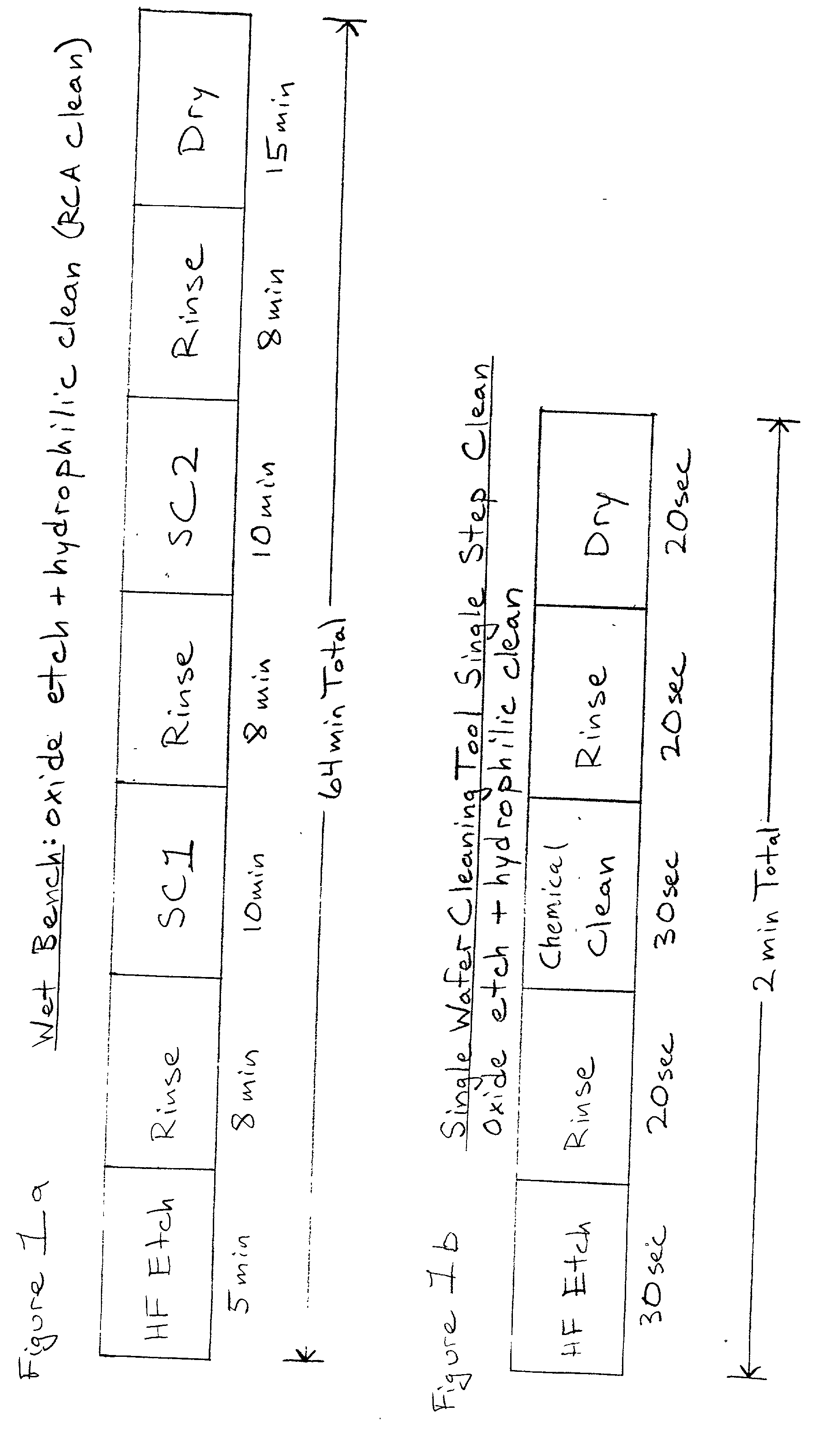
[0053] the present invention where the use of the single wafer cleaning tool and process is particularly useful is a combination of using hydrofluoric acid (HF) to strip an oxide surface of a wafer and using the modified cleaning solution as described above to clean the wafer in less than two minutes. This application is illustrated by a flow-chart in FIG. 8. In the first step 800 the wafer is placed in the single wafer cleaning tool. A substrate or wafer requiring cleaning is clamped face up to wafer support 610. Next, the wafer is subjected to an HF step 810. During the HF step 810 the wafer is spun at a rate between 10-2000 rpm, and preferably 100-1000 rpm, as diluted HF is fed through nozzle 614 and sprayed onto the top surface of wafer 608 to form an HF solution cover 622 over the entire front side of wafer 608. The HF solution may have a concentration in the range of 5-1000 parts water to one part HF. The HF solution is comprised of preferably 50 parts DI water to one part HF....
second embodiment
[0065] the current invention, shown in FIG. 9 in flow chart form, is a process which can be used to make the surface of the wafer hydrophobic. Instead of performing the HF step and then the chemical cleaning step, as set forth in FIG. 8, this process places the cleaning step before the HF step. Performing the HF step after the cleaning step leaves the surface of the wafer hydrophobic at the end of the cleaning process. All of the same details as described above with respect to FIG. 8 apply to the respective steps in the current process. The wafer is first placed in the single wafer cleaning tool by clamping the wafer face up to wafer support 610 (step 900.) The wafer is then spun as described above. The cleaning solution of the present invention, that optionally contains a cavitation gas, is then fed through nozzle 614 onto the top surface of wafer 608 as set forth in chemical cleaning step 910. Next, the wafer is rinsed in step 920 with a rinse that optionally contains an oxidant a...
third embodiment
[0066] the present invention, as shown in the flow chart in FIG. 11, is the use of the single wafer cleaning tool after an O.sub.2 ashing of the wafer to remove a photoresist. Most O.sub.2 plasma ashing steps are carried out in a single wafer mode and it is therefore very useful to have a single wafer cleaning method instead of a batch cleaning method after a O.sub.2 plasma ashing step. All of the same details as described above apply to the respective steps in the current process. The most significant difference in this process compared to the others disclosed in the present invention is that there is no HF step. There is no HF step is because the oxide surface on the wafer is needed in subsequent processing. In this application, after the O.sub.2 ashing step 1100, a wafer having an outer oxide film on a silicon surface is placed in the single wafer cleaning tool face up as described above and the wafer is spun. Next, as set forth in chemical cleaning step 1110, the wafer is cleane...
PUM
| Property | Measurement | Unit |
|---|---|---|
| Fraction | aaaaa | aaaaa |
| Fraction | aaaaa | aaaaa |
| Fraction | aaaaa | aaaaa |
Abstract
Description
Claims
Application Information
 - R&D
- Intellectual Property
- Life Sciences
- Materials
- Tech Scout
- Unparalleled Data Quality
- Higher Quality Content
- 60% Fewer Hallucinations
Browse by: Latest US Patents, China's latest patents, Technical Efficacy Thesaurus, Application Domain, Technology Topic, Popular Technical Reports.
© 2025 PatSnap. All rights reserved.Legal|Privacy policy|Modern Slavery Act Transparency Statement|Sitemap|About US| Contact US: help@patsnap.com


