Orthopedic implant and method of making metal articles

Inactive Publication Date: 2002-09-12
DEPUY ACROMED INC
View PDF0 Cites 229 Cited by
  • Summary
  • Abstract
  • Description
  • Claims
  • Application Information

AI Technical Summary

Benefits of technology

0025] In another embodiment, the present application is directed to a method of making an article. The method includes directing a stream of a particulate material at a rate greater than about 4 grams per minute and less than about 20 grams per minute and moving the stream in a pattern corresponding to at least a portion of

Problems solved by technology

One issue with presently available implants for arthroplasty is that they may result in stress shielding, meaning that a stress normally felt by bone adjacent to the implant is reduced due to the stiffness of the implant.
When a bone is shielded from physiologic loads, it typically reduces in size and strength according to Wolff's Law, thereby increasing the chance of its breakage.
Disc collapse or narrowing reduces the space between vertebrae, and damage to the disc can cause it to bulge or rupture, possibly extruding into the spinal canal or neural foramen.
These changes can cause debilitating pain, numbness, or weakness.
Both spinal fusion, such as disclosed by Michelson, and the use of spacers, such as disclosed by Biedermann, limit the mobility of the spine by fixing two adjacent vertebrae relative to one another.
In addition to reduced mobility, these arrangements do not compensate for the shock absorption lost when a disc is damaged or removed.
However, the complex load bearing behavior of a disc has not been successfully reproduced with an elastomer, and such implants are prone to wear and failure.
These implants are subject to failure by rupture or drying out, just like a disc.
In addition to failing to accurately perform the functions of the replaced disc, these structures are multi-component and particles generated by wear of articulating components can result in ad

Method used


Image

  • Orthopedic implant and method of making metal articles
  • Orthopedic implant and method of making metal articles
  • Orthopedic implant and method of making metal articles

Examples


example 1

[0107] One suitable construction of an implant having a shape and design substantially in accordance with the present application is provided by the following combination of elements.

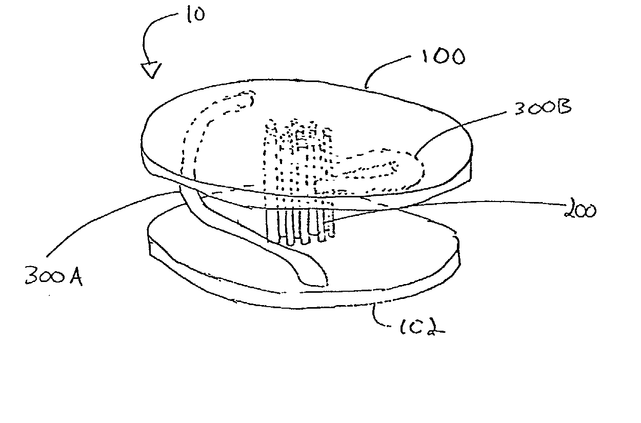
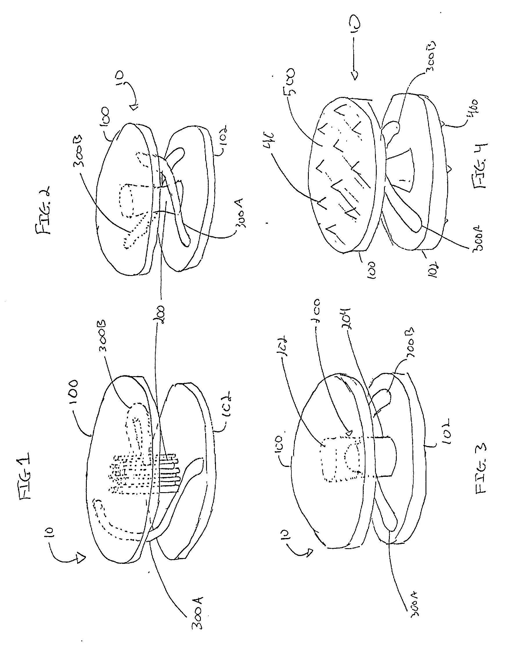
[0108] An implant 10 to be used in a spinal arthroplasty includes a first plate 100 and a second plate 102. Plates 100, 102 are substantially oval and planar and are sized to fit within a human spinal column in a space previously occupied by a disc. The outer planar surfaces of plates 100, 102 are provided with protrusions 400 consisting of teeth and a tissue ingrowth region 500 consisting of a textured surface.

[0109] Implant 10 also includes an axial support 200, between, and connecting, plates 100, 102. Axial support 200 is oriented in the center of plates 100, 102 and includes a cable incorporated at both ends to plates 100, 102. Implant 10 further includes two torsional supports 300A, 300B. Torsional supports 300A, 300B are unitarily formed with plates 100, 102 and curve around axial support 200 suc...

examples 2-7

[0111] In order to determine what values for .PHI. produce acceptable build height and preferred microstructure, a series of six examples, numbered 2-7, were made with varied parameters. For all six examples a titanium alloy containing 6% aluminum and 4% vanadium was used. The article constructed in each example was 0.0127 m.times.0.0127 m.times.0.019 m. The build parameters and resultant microstructure are shown in Table 1.

3TABLE 1 Preferred Powder Micro- Laser Speed Feed Rate .PHI. structure In Method Example Power (J / s) (m / s) (kg / s) (.times. 10.sup.6) Microstructure range Range 2 342 0.0254 0.00013 9.8 Refined .beta. grain structure .check mark. .check mark. (comprising 71.3%) 3 415 0.03387 0.000152 10.76 Refined .beta. grain structure .check mark. .check mark. (comprising 76.9%) 4 342 0.0254 0.00013 9.9 Refined .beta. grain structure .check mark. .check mark. (comprising 65.2%) 5 342 0.0339 0.00016 9.3 Large columnar .beta. grain structure, X .check mark. (refined .beta. grain s...

example 8

[0114] In order to determine the yield load, strain data and displacement of the embodiment of the application illustrated in FIGS. 19-21, the implant was tested under axial compressive loading and compressive loading 45 degrees from axial. The implant was constructed of titanium alloy containing 6% aluminum and 4% vanadium using the LENS process and had the preferred microstructure of the invention. The dimensions of the article tested were identical to that given in Table 3, except that the thickness of the swept structure was constant along its length at 2.1 mm.

[0115] Under axial testing, none of three specimens failed at loads up to 8900 N, but did incur permanent deformation on the order of 1.3 mm, or 11% of the original device height. Parts showed yielding at approximately 3560 N, exceeding the expected 3000 N yield resistance.

[0116] Under testing 45 degrees from axial, none of three specimens failed at loads up to 8900 N, but did incur permanent deformation on the order of 1....


PUM

PropertyMeasurementUnit
Fractionaaaaaaaaaa
Fractionaaaaaaaaaa
Fractionaaaaaaaaaa

Abstract

The present application is directed to an orthopedic implant. More specifically, the orthopedic implant is suitable for arthroplasty procedures where optimized multifunctional behavior of the implant is desired. In some embodiments the implant is suitable for the replacement of a spinal disc. In one embodiment, the present application is directed to an orthopedic implant including a first plate a second plate and a flexible support. The flexible support may have a single connection to the first plate and a single connection to the second plate and may vary in cross section. The first plate, the second plate and the flexible support may be unitarily formed. This application is also directed to methods of producing metal articles having microstructure for improved mechanical properties. Such methods may be suitable for the production of medical devices. In one embodiment, the method includes directing a stream including a particulate material in a pattern corresponding to at least a portion of a structure of an orthopedic implant and fusing at least a portion of the particulate material with a laser.

Description

[0001] This patent application claims priority to U.S. patent application Ser. No. 09 / 588,167, filed Jun. 5, 2000, and to U.S. Provisional Patent Application No. 60 / 291,183, filed May 15, 2001.BACKGROUND[0002] 1. Field[0003] This application is directed to an orthopedic implant. More specifically, the orthopedic implant is suitable for arthroplasty procedures where optimized multifunctional behavior of the implant is desired. In some embodiments the implant is suitable for the replacement of a spinal disc. This application is also directed to methods of producing metal articles having microstructure for improved mechanical properties. Such methods may be suitable for the production of medical devices.[0004] 2. Description of the Related Art[0005] Orthopedic implants have been used to repair damage to the skeleton and related structures, and to restore mobility and function. For example, various devices, such as pins, rods, surgical mesh and screws, have been used to join fractured b...

Claims


Application Information

Patent Timeline
IPC IPC(8): A61B17/86A61F2/00A61F2/30A61F2/44B22F3/105B29C67/00
CPCA61B17/86A61F2/3094A61F2/30942A61F2/30965A61F2/442A61F2/4425A61F2002/30014A61F2002/30018A61F2002/30085A61F2002/30125A61F2002/30135A61F2002/30225A61F2002/30329A61F2002/30563A61F2002/30565A61F2002/30571A61F2002/30662A61F2002/30777A61F2002/30785A61F2002/30841A61F2002/30892A61F2002/30904A61F2002/3092A61F2002/30968A61F2002/3097A61F2002/30971A61F2002/443A61F2220/0025A61F2230/0004A61F2230/0008A61F2230/0069A61F2250/0018A61F2250/0029A61F2310/00023A61F2310/00179B22F3/1055B22F2003/1057Y02P10/295B29C64/153A61F2002/30084A61F2002/30136Y02P10/25B22F10/28B22F10/64B22F10/36B22F10/366B22F10/25
Inventor MANASAS, MARKOSLAKOVIC, KEITH E.SULTAN, CORNELHAMILTON, JOHN V.INGBER, DONALD E.SAMMARCO, CARMINEKUMMAILIL, JOHNSKINNER, DAVID J.
Owner DEPUY ACROMED INC
Why Eureka
Try Eureka