
Air cleaner assembly with disposable environmentally friendly filter element

Inactive Publication Date: 2002-11-14
PHELPS ALBERT CAROLL
View PDF13 Cites 8 Cited by
  • Summary
  • Abstract
  • Description
  • Claims
  • Application Information

AI Technical Summary

Benefits of technology

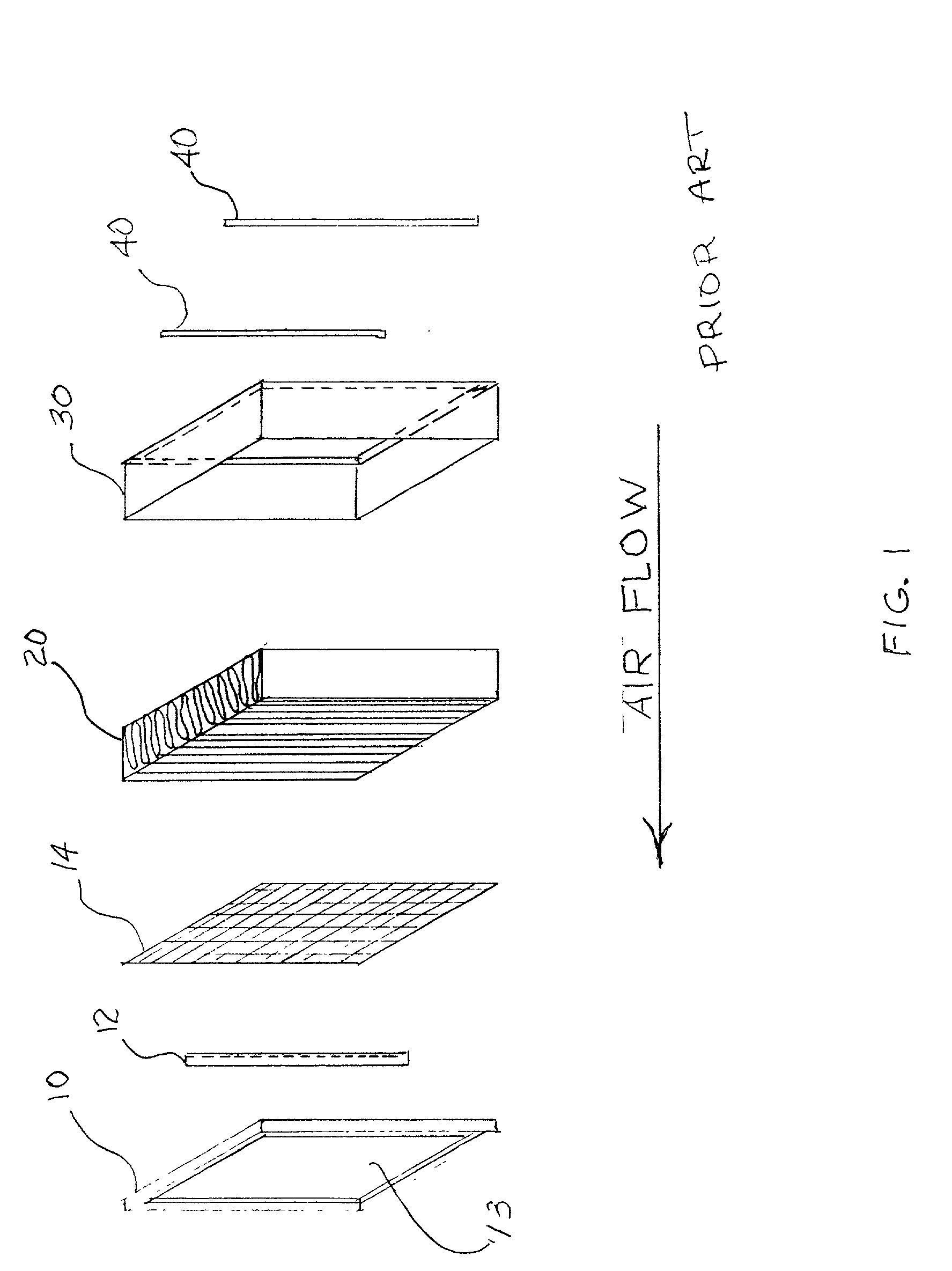
[0043] Principal objects and advantages of the improved air cleaner assembly include:[0044] 1. It is one objective to eliminate metals internal in the pleated paper panel air cleaner element itself.[0045] 2. It is another objective to reduce the number of parts required to manufacture the present air cleaner element, thus saving materials and labor for the assembly of the present air cleaner element.[0046] 3. It is a further objective to reduce the weight and increase the density of disposable materials eventually requiring disposal in a landfill site or at the incinerator.[0047] 4. It is a further objective to eliminate or limit to trace amounts plasticizers and chlorine based materials integral to the disposable element which can become PCB precursors upon disposal.[0048] 5. It is still another objective to provide a filter element with a seal which effectively prevents leakage of unfiltered air into the plenum exit.[0049] 6. It is a mandatory objective to provide a system of retrofit of existing installations at a one-time minimum cost.[0050] 7. It is another objective to increase the effective filtration area of the panel by elimination of blocking stiffener sheet metal strips and expanded metal facings.[0051] 8. It is a mandatory objective to provide a construction which can be incorporated into new production of air cleaner assemblies with little change and at reduced manufacturing cost which will accept the improved replacement air filter element.[0052] 9. It is a final objective to maintain the properties of strength and ruggedness of the metal portions of the air cleaner element by transferring them from forming an internal skeleton which is disposed of in a spent air cleaner element, and hence becoming ecologically more undesirable waste upon disposal, to the interior of the air cleaner assembly housing as a permanent exoskeleton support structure, thereby reducing the environmental load to primarily organic materials which will decompose or incinerate under proper conditions to benign elements.

Problems solved by technology

Such engines are often used in harsh environments such as deserts, where extreme loads of particulate matter occur frequently and must be trapped by air filter elements within the air cleaner assembly.
Further complicating the operating conditions are rapidly shifting loads on the engine, causing pulsations on mass flow of the intake air, subjecting the filter element to large flexions unless strongly supported.
In general, the air cleaner element must survive extreme conditions in an unattended state, hence the rugged construction This rugged construction comes at a price.
This element is intended to be disposable in nature, as most field conditions do not allow for washing or otherwise maintaining a cleanable element.
Each time such a unit is replaced, a significant amount of undesirable metals forming the internal support structure and adhesives generally containing chlorine and plasticizer are placed in the landfill or more often in other areas of the world in the incinerator.
This environmental loading in more populous areas of the world, particularly in Europe, has led to pay-as-you-pollute regulation as well as punitive associated costs, necessitating significant disposal expense for the user of the present air cleaner system.
Transportation of essential incoming operating supplies and the mandatory removal of wastes is exceptionally costly.
These internally disposed elements are generally of metals such as steel, zinc, aluminum, and are definitely ecological undesirables upon disposal.
Protruding fingers between each pleat would be difficult to impossible to insert into the densely packed internal combustion engine pleated media pack.
It is believed that such an arrangement for the assembly with the common closely spaced pleats associated with combustion air for internal combustion engines would preclude use of this support arrangement, in addition there would be a degradation of favorable depth / length of section ratio.
Again this will not withstand mass flow conditions of internal combustion engines utilizing wide dimensions.
The individual cross wires do support the media across the entire crest and root of the width but provide for relatively few pleats, therefore it is infeasible for the closely spaced pleats typical in internal combustion filter elements.
In addition, unless the wire were excessive in diameter, or otherwise supported, long spans across the width would be easily deflected, allowing for excessive deflection in the pleated media element.
1. U.S. Pat. No. 6,045,597(Choi) which teaches a support / spacer is expected to be internally fixed and therefore expended with a disposable filter assembly. The spacer / support is taught to be made from low elastic modulus material primarily of plastic and does not maximize section modulus nor maximize depth / length ratios, however it is disposed in the width dimension of the filter.
2. U.S. Pat. No. 6,036,752(Reuter) teaches a support / spacer means expected to deform in a predictable manner.
It is again a HVAC type filter with system characteristics of steady air flow and low velocities, making it unsuitable for the oscillation of the internal combustion engine airflows.
The glued pocket arrangement would probably be prone to fatigue and failure under the conditions characteristic of the internal combustion engine intake.
Occasionally one sees a separate gasket, however this is risky as sometimes it is lost, or misaligned, resulting in seal leakage.
This design lends itself to mis-alignment and improper sealing.
Face seals alone tend to have less than maximum sealing effectiveness, unless some method of compression pressure control is inherant.
These newer seals tend to be less forgiving of overpressures, as significant plastic creep, stress cracking, or other failures result from overpressure, and unsealed face areas or gaps result from under compression.
This method entails several machined parts, a spring, and a metal stamping and would be relatively expensive to manufacture due to the number of parts required and probably difficult to use under outdoor field conditions.

Method used


Image

  • Air cleaner assembly with disposable environmentally friendly filter element
  • Air cleaner assembly with disposable environmentally friendly filter element
  • Air cleaner assembly with disposable environmentally friendly filter element

Examples


Embodiment Construction

[0128] A preferred embodiment of the invention is illustrated in the exploded drawing of FIG. 13.

[0129] A prior art plenum chamber (50,55) already has a compression area weldment (53) opposing the flow of incoming air. This compression weldment(53) has, opposing the airflow and normal to it, an intake face(57).

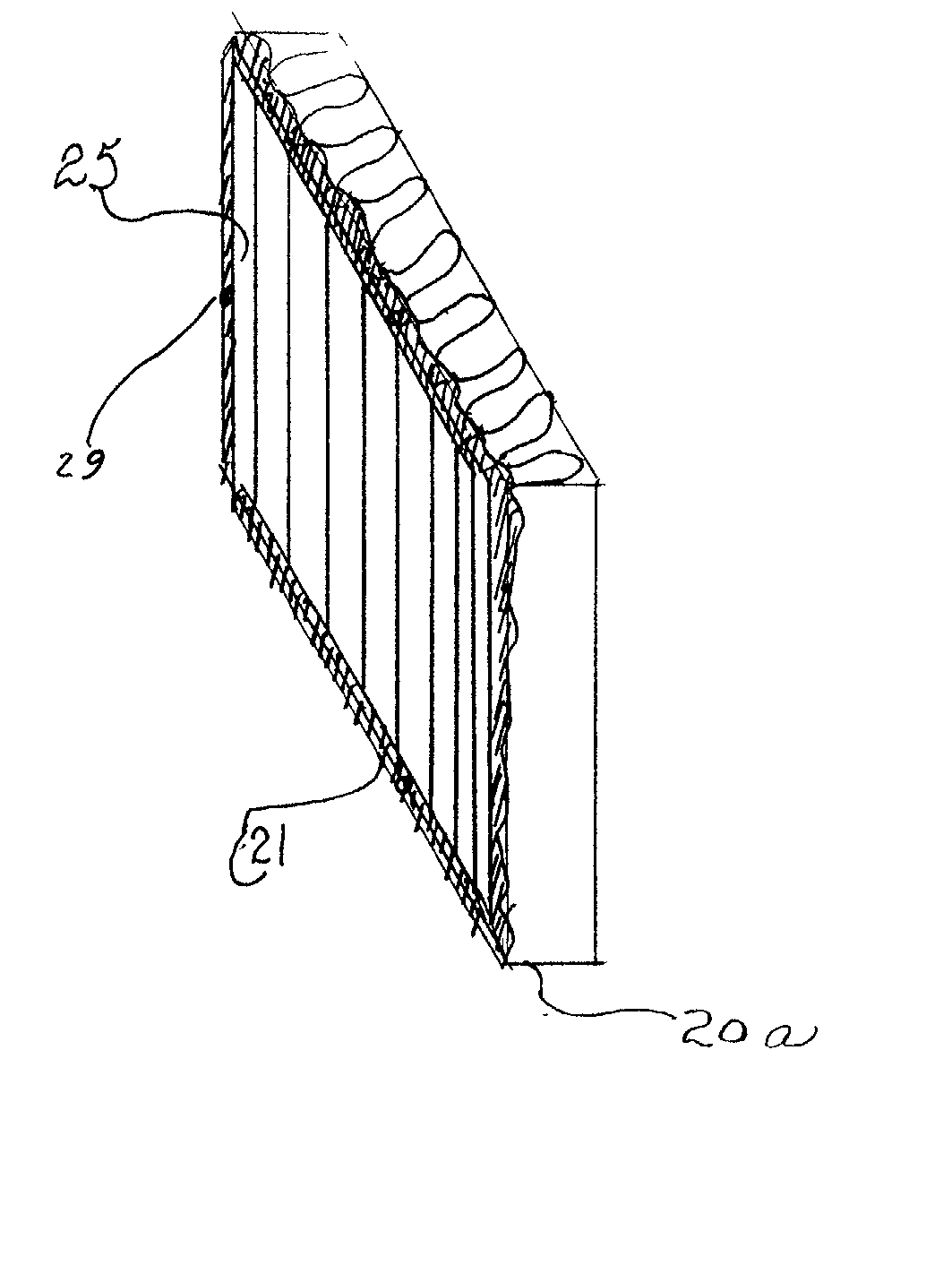
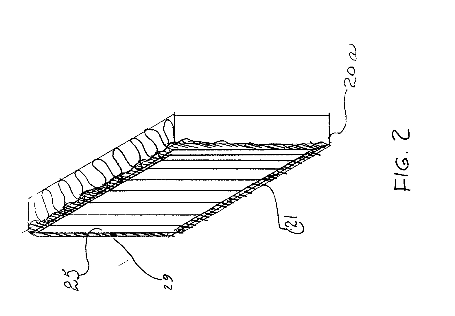
[0130] An edge-glued media pack assembly(20a), with molded in place gasket, is pre-assembled with a compression spacer(90) of FIG. 11. The hem(94) of the compression spacer is sized to fit into the edge-glued media pack of FIG. 4 into the retaining groove(27), and to stop on the bottom of the molded in retaining groove(23).

[0131] A field installed stiffener support is centered on the edge-glued media pack assembly(20a) by inserting the tops of the plural respective girder trusses(82), between openings in the filter air exiting area (25), between pleats of the edge-glued media pack assembly (20a), until the top sealing surface (81) of the field installed stiffener support of FI...


PUM

PropertyMeasurementUnit
Pressureaaaaaaaaaa
Lengthaaaaaaaaaa
Electrical resistanceaaaaaaaaaa

Abstract

An improved air cleaner assembly for large displacement stationary engines provides for an included environmentally friendly disposable filter element containing substantially no chlorine compounds or structural metal supports which upon incineration or landfilling become undesireable chemical compounds. Improved sealing results by creating novel gasket compression control both radially and by a face seal by use of permanent metal components which are not discarded as before. Excessive compression of the gasket material is prevented by structure integral to the air cleaner assembly, and support of the filter element is external within the air cleaner assembly rather than internal within the filter element, thus eliminating the manufacturing cost of metal components previously discarded as integral to the filter element upon replacement of the disposable filter element.

Description

[0001] This application is entitled to the benefit of Provisional Patent Application Serial No. 60 / 281,879, Filed Apr. 5, 2001.[0002] 1. Field of Invention[0003] The invention relates to an improved air cleaner assembly for internal combustion engines utilizing pleated media panel type air filter elements whose narrower dimension exceeds 10 inches in width.[0004] 2. Prior Art[0005] Large stationary engines typically found in the extractive operations of the petroleum industry are used in the field for various power applications such as compression of natural gas, pumping operations, and electrical power generation among others. Such engines are often used in harsh environments such as deserts, where extreme loads of particulate matter occur frequently and must be trapped by air filter elements within the air cleaner assembly. These engines are large displacement engines requiring large volumes of combustion air. As a result, the densely pleated panel type air filter element with lar...

Claims


Application Information

Patent Timeline
IPC IPC(8): B01D46/00B01D46/52F02M35/024
CPCB01D46/0091B01D46/521F02M35/10275B01D2279/60F02M35/024B01D2271/02
Inventor PHELPS, ALBERT CAROLL
Owner PHELPS ALBERT CAROLL
Learn More