
Polarisers and mass-production method and apparatus for polarisers

a technology of polarisers and mass production methods, applied in the direction of optics, instruments, other domestic articles, etc., can solve the problems of wavelength range, transmission and temperature stability limitations,

Inactive Publication Date: 2002-12-19
CSEM CENT SUISSE DELECTRONIQUE & DE MICROTECHNIQUE SA RECH & DEV
View PDF9 Cites 68 Cited by
  • Summary
  • Abstract
  • Description
  • Claims
  • Application Information

AI Technical Summary

Benefits of technology

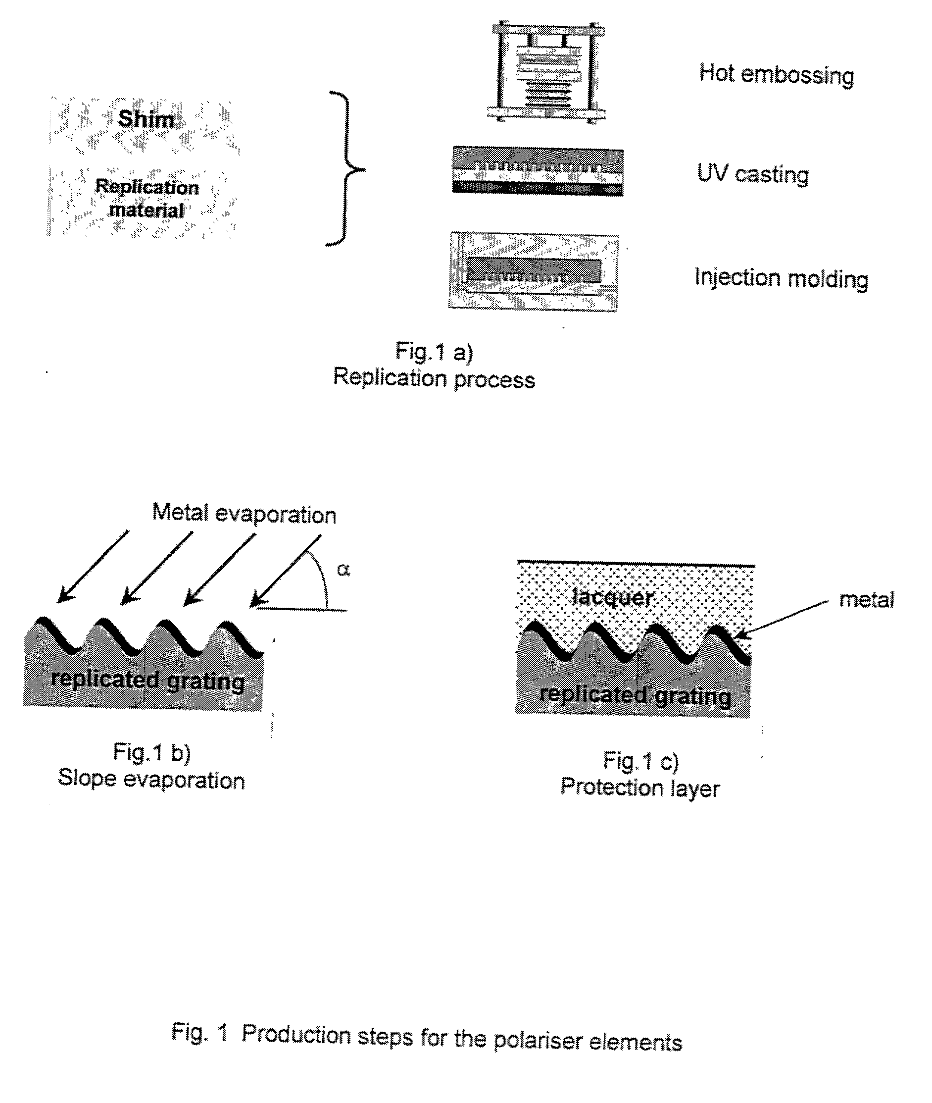
[0014] Replication technologies such as hot embossing, UV-casting and injection moulding are suitable for low-cost production of such gratings [5]. The replication mould (shim) can be fabricated from an original microstructure using holographic lithography. Such replication technologies are capable of reproducing very high-resolution surface microstructure (feature sizes <100 nm) at very low cots in volume. Typical materials are polymers such as polycarbonate and PMMA (polymethyl methacrylate).
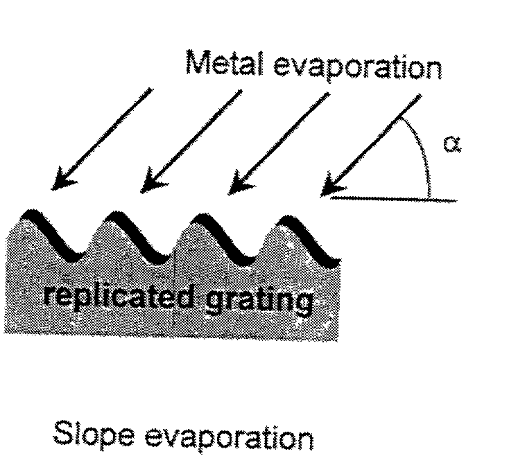
[0035] A method for the mass-production of transmissive, subwavelength, metal-grating polarisers for the visible, near and mid infrared wavelengths has been described. The polarisers are realised by the slope evaporation of a specific metal onto a substrate with microstructured surface, which has been optimised using rigorous diffraction theory, in the form of a subwavelength grating. The substrates can be mass-produced by high-resolution replication processes such as hot embossing or injection moulding. An additional surface protection layer may be used to give good wear, stability and lifetime properties; this protection layer prevents the oxidation of the subwavelength grating metal, and it also allows cleaning of the top surface. The optical effects of this optional surface protection layer are taken into account in the optimisation process using rigorous diffraction theory. By suitable choice of materials, polariser elements with an operating temperature range well above 100.degree. C. can also be realised. The structure and production method is well suited to low-cost, mass production of the polariser elements.

Problems solved by technology

Control of the polarisation of transmitted light at visible and at near / mid infra-red (wavelength range of about 700-2000 nm) is an important issue in many optical systems.
The most widespread sheet polarisers are of the `Polaroid` type, and suffer from limitations in the wavelength range, transmission and in the temperature stability.

Method used


Image

  • Polarisers and mass-production method and apparatus for polarisers
  • Polarisers and mass-production method and apparatus for polarisers
  • Polarisers and mass-production method and apparatus for polarisers

Examples


example 2

[0029] Effect of Optimisation of Grating Relief Profile:

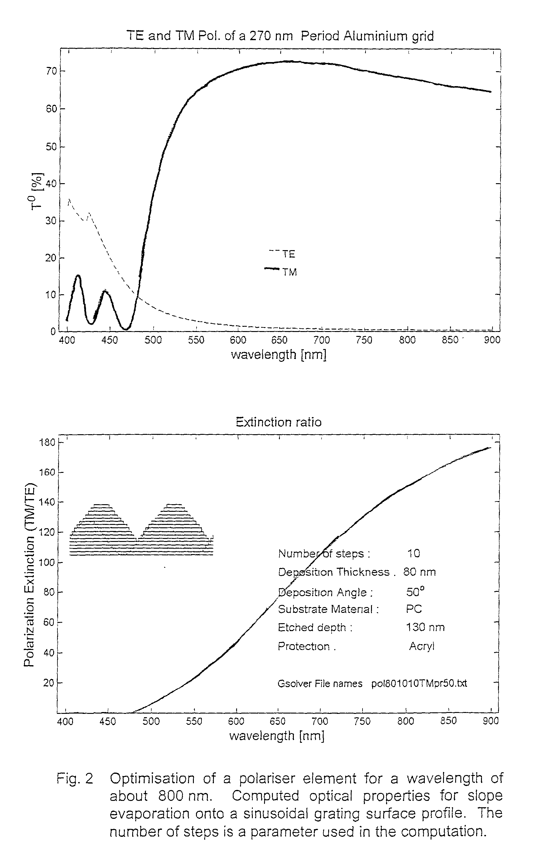
[0030] FIG. 3 shows a polariser design using slope evaporation onto a sinusoidal grating profile. The computation is based on rigorous diffraction theory and takes into account the evaporated metal cross-section as evaporated onto the replicated grating profile, in this case sinusoidal, as well as the protective overcoat of an acrylic-based polymer. A maximum transmission TM of about 65% and an extinction ration TM / TE of about 340 over the wavelength range shown is achieved for an optimised metal thickness for this profile.

[0031] FIG. 4 shows the result of optimising the replicated grating relief profile. The deposited metal cross-section is changed, resulting in a maximum transmission TM of about 76% and an extinction ration TM / TE in excess of 480, a significant improvement in the polariser performance.

[0032] A further improvement may be obtained by replacing the acrylic-based overcoat by an evaporated MgF.sub.2 (Magnesium Flu...


PUM


Abstract

A method of mass producing polarizes comprises designing by rigorous diffraction theory an optimized grating profile, replicating the profile in a polymer or other substrate, and slope evaporating a metal onto the substrate. The angle of slope evaporation, the metal, and the thickness of the metal are optimized for a given wavelength using rigorous diffraction theory. The polarizer may be coated with a protective coating, such as an acrylic based lacquer or Magnesium Fluoride (MgF2). The optical effect of the coating is also taken into account in the design using rigorous diffraction theory.

Description

[0001] The invention is relevant for the fabrication of polariser elements for applications in optical systems for areas such as telecommunications, flat panel and other liquid crystal displays, sensors, optical instruments and lasers.PRIOR ART[0002] Control of the polarisation of transmitted light at visible and at near / mid infra-red (wavelength range of about 700-2000 nm) is an important issue in many optical systems. The most widespread sheet polarisers are of the `Polaroid` type, and suffer from limitations in the wavelength range, transmission and in the temperature stability. The use of very fine surface structures with micrometer or sub micrometer feature size for realising specific optical properties is well known. Typical applications are anti-reflection behaviour [1] and wavelength control. The use of very fine metal gratings for realising polariser properties is also well known [2,3]. Fabrication techniques to date for sub-micrometer period gratings have been based upon h...

Claims


Application Information

Patent Timeline
IPC IPC(8): G02B5/18G02B5/30
CPCG02B5/3058G02B5/1847
Inventor GALE, MICHAELSOECHTIG, JURGENZSCHOKKE, CHRISTIANSCHNIEPER, MARC
Owner CSEM CENT SUISSE DELECTRONIQUE & DE MICROTECHNIQUE SA RECH & DEV
Learn More