Hard pipe cutting equipment

a cutting equipment and hard pipe technology, applied in the direction of manufacturing tools, other manufacturing equipment/tools, tube shearing machines, etc., can solve the problems of trivial and ineffective procedures, hazardous to operators, and apt environment, so as to improve the holding capacity and cutting quality, and shorten the distance between holding points and turning positions

Inactive Publication Date: 2003-01-09
NANYA PLASTICS CORP
View PDF0 Cites 45 Cited by
  • Summary
  • Abstract
  • Description
  • Claims
  • Application Information

AI Technical Summary

Benefits of technology

0032] FIG. 10 is an assembly drawing of the table and the cuttings collector of the present invention. The cuttings produced from turning are collected by the cuttings collector 55 which is connected to the cuttings collecting wind shield 54 installed below the bottom plate 71. The cuttings do not fall down to the floor since the overall cutting operation takes place in a closed space (safety shield 53); besides, all the cuttings are collected by the cuttings collector 55. In addition, the turning operation of the cutting blade and the chamfering blade will not produce dust, which is an extra advantage for pollution control.
0033] FIG. 11 is an assembly drawing of the output clamp apparatus fixing mechanism of the present invention, which comprises an output clamp apparatus fixing seat 56, a plurality of output clamp apparatus sliding track 57, an output clamp apparatus sliding seat 58, an output clamp apparatus 59, an output clamp apparatus drive rotating disc 61, and an output clamp apparatus driving cylinder 60. The output clamp apparatus driving cylinder 60 drives the output clamp apparatus drive rotating disc 61 to further drive a plurality of output clamp apparatus driving roll wheels 62 to further drive the output clamp apparatus sliding seat 58 and the output clamp apparatus 59 to hold the hard pipe 21, the function of which is that both the hard pipe 21 and the main table (FIG. 9) are concentric while cutting and no problems such as bias and displacement will happen, i.e., the function of which is positioning. A plurality of longer output clamp apparatus 59 simultaneously hold the hard pipe 21 at several different points to shorten the distance between holding points and turning positions so as to improve the holding capability and the cutting quality, which constitutes the characteristics of the present invention.
0034] FIG. 12 is an assembly drawing of the input V shape rolling wheel of the present invention, which comprises an input V shape leading wheel and an input V shape leading wheel fixing seat. The function is to prevent the hard pipe 21, while being input of being cut, from colliding with the input clamp apparatus fixing mechanism (FIG. 5) and with the replaceable cutting blade and the chamfering blade fitted to the cutting sliding seat fix rotating disc 31; the blade may be damaged otherwise.

Problems solved by technology

The procedure is trivial and without efficiency.
Besides, the operation environment is apt to be polluted by cuttings since the cutting operation is exposed to the atmosphere, which is consequently hazardous to operators.

Method used


Image

  • Hard pipe cutting equipment
  • Hard pipe cutting equipment
  • Hard pipe cutting equipment

Examples


example 2

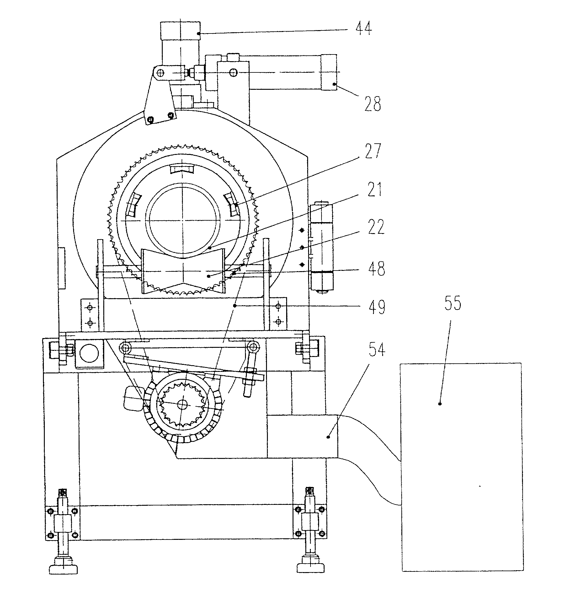
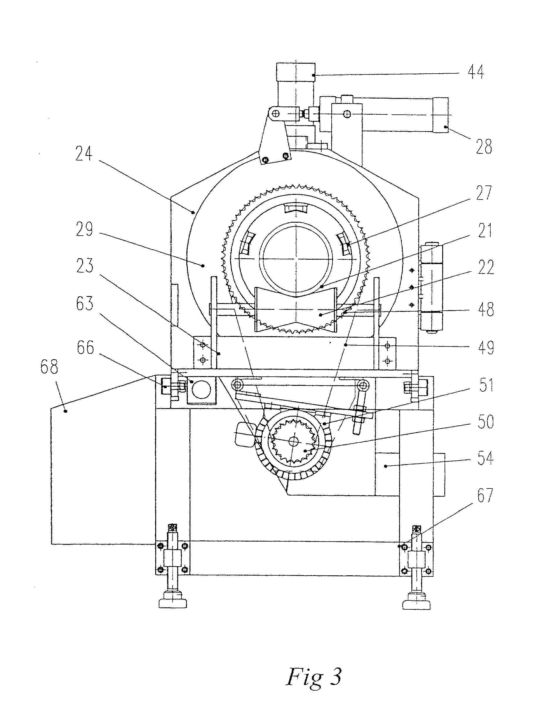
[0037] While it is intended to produce an eight inches hard pipe, the eight inches hard pipe is led first by a leading machine at the previous stage; then, the hard pipe goes through the front-end input V shape leading wheel, the input clamp apparatus fixing mechanism, the transmission mechanism, the cutting mechanism, the main table, the output clamp apparatus fixing mechanism, the output V shape leading plate, the leading wheel, finally reaches the multiple-unloading frame at the rear stage and touches the limit switch for spacing and cutting so as to initiate the electric control system for cutting,

[0038] meanwhile the input clamp apparatus fixing mechanism and the output clamp apparatus fixing mechanism operate to hold the hard pipe, and to initiate the variable frequency driving motor to operate; the blade-feeding cylinder drives the blade-feeding roll wheel according to the preset input so as to push the blade-feeding pushing rotating disc move forward to further drive the twi...


PUM

PropertyMeasurementUnit
pressureaaaaaaaaaa
holding pressureaaaaaaaaaa
thicknessaaaaaaaaaa

Abstract

The present invention relates to a novel cutting equipment, which automatically cuts hard plastic pipes produced from an extruder, having a table, an input V shape leading wheel, an input fixing clamp apparatus mechanism, a cutting mechanism, a bearing transmission mechanism, an output fixing clamp apparatus mechanism, a V shape leading plate, a leading wheel, a cuttings collector, and an electric control system, which are assembled to a novel means of a hard pipe cutting machine.

Description

[0001] 1.Field of the Invention[0002] The present invention relates to a cutting machine, in particular, which is capable of automatically cutting hard plastic pipes produced from an extruder.[0003] 2.Description of the Related Prior Arts[0004] The conventional hard pipe cutting equipment is generally manual, or semiautomatic, or automatic, wherein one of the automatic equipment is to cut, for small diameter pipes only, with a disc cutting apparatus (shown as FIG. 1) by way of rolling (shown as FIG. 2) which is not able to cut big diameter pipes. In addition, said equipment does not have chamfer means so that it can only cut without chamfering which makes it disable to cut medium and big diameter hard pipes. As for the semiautomatic equipment, which executes cutting by the coordination of a simple mechanism and a large cutting apparatus, the product of which needs to be further processed. The procedure is trivial and without efficiency. Besides, the operation environment is apt to b...

Claims


Application Information

Patent Timeline
Patent Type & Authority Applications(United States)
IPC IPC(8): B23B5/16B23D21/00B23D21/04B26D3/16B26D7/02B26D7/06
CPCB23B5/16Y10T409/3042B23D21/006B23D21/04B26D3/16B26D3/166B26D7/02B26D7/06B26D2007/013Y10T82/16967Y10T29/5147Y10T409/306048Y10T29/5199Y10T409/304144Y10T82/16229B23B2260/116
Inventor CHANG, SHIN-FA
Owner NANYA PLASTICS CORP
Why Eureka
Try Eureka