Reactor filled with solid particle and gas-phase catalytic oxidation with the reactor

a gas-phase catalytic oxidation and reactor technology, which is applied in the direction of indirect heat exchangers, lighting and heating apparatus, carboxylic compound preparation, etc., can solve the problems of difficult to coincide the pressure drop of the measuring reaction tube with that of the non-measuring reaction tube, and the heat-efficiency is not reduced to achieve cooling or heating,

Inactive Publication Date: 2003-01-09
NIPPON SHOKUBAI CO LTD
View PDF3 Cites 36 Cited by
  • Summary
  • Abstract
  • Description
  • Claims
  • Application Information

AI Technical Summary

Problems solved by technology

However, such a thermometer has a drawback that the thermometer occupies a certain volume in the reaction tube, hence a pressure profile along with the axis is generally affected, and accordingly behavior for the pressure drop of the reaction tube in which the thermometer is placed is allowed to change.
Though sequential changes of pressure drops at solid particle layers in operations is very valuable for obtain the conditions of solid particles, the same problem as the thermometer is in the case of setting pressure measuring devices into the reaction tubes.
Adversely, if the size exceeds 20 mm, heat-efficiency lowers not to achieve cooling or heating.
If the diameter exceeds 10 mm, it becomes difficult for the pressure drop of the measuring reaction tube to coincide with that of the non-measuring reaction tube.
If this reduction is unduly large, the excess will be at a disadvantage in aggravating the pressure drop.
Conversely, if it exceeds 99.5%, the excess will be at disadvantages in lowering the function of capturing the impurities and degrading the function of cooling the reaction gas by the second inert particle layer as well.

Method used


Image

  • Reactor filled with solid particle and gas-phase catalytic oxidation with the reactor
  • Reactor filled with solid particle and gas-phase catalytic oxidation with the reactor
  • Reactor filled with solid particle and gas-phase catalytic oxidation with the reactor

Examples


referential example 1

Production of Upstream Catalyst

[0106] In 150 liters of purified water kept heated and stirred, 100 kg of ammonium molybdate, 6.3 kg of ammonium paratungstate, and 13.7 kg of nickel nitrate were dissolved. To the resultant solution, an aqueous nitrate solution prepared by mixing a solution of 68.7 kg of cobalt nitrate in 100 liters of purified water, a solution of 19 kg of ferric nitrate in 30 liters of purified water, and a solution of 27.5 kg of bismuth nitrate in 30 liters of purified water incorporating therein 6 liters of concentrated nitric acid was added dropwise. Then, a solution of 14.2 kg of an aqueous 20 wt. % silica sol solution and 0.29 kg of potassium nitrate in 15 liters of purified water was added. The suspension thus obtained was heated and stirred till vaporization to dryness and then dried and pulverized. The produced powder was molded into cylinders 5 mm.+-.10% in diameter and 7 mm.+-.10% in length and calcined as swept with air at 460.degree. C. for six hours to ...

referential example 2

Production of Downstream Catalyst

[0107] In 500 liters of purified water kept heated and stirred, 100 kg of ammonium molybdate, 12.7 kg of ammonium paratungstate, and 27.6 kg of ammonium metavanadate were dissolved. To the resultant solution, a solution of 20.5 kg of copper nitrate and 1.4 kg of antimony trioxide in 50 liters of purified water were added. This mixed solution and 350 kg of a silica-alumina carrier having an average particle diameter of 5 mm .+-.10% were evaporated together to dryness to have a catalytic component deposited on the carrier and then calcined at 400.degree. C. for six hours to afford a catalyst. The catalyst in a required amount was obtained by repeating this process. This catalyst had this molar composition: Mo 12, V 5.0, W 1.0, Cu 2.2, Sb 0.2.

Inert Particle

[0108] Raschig rings of stainless steel having 6 mm.+-.0.5 mm in outer diameter, and 6 mm.+-.0.5 mm in length (available from IWAO JIKI K.K. in Japan) are used as the inert particle.

example 1

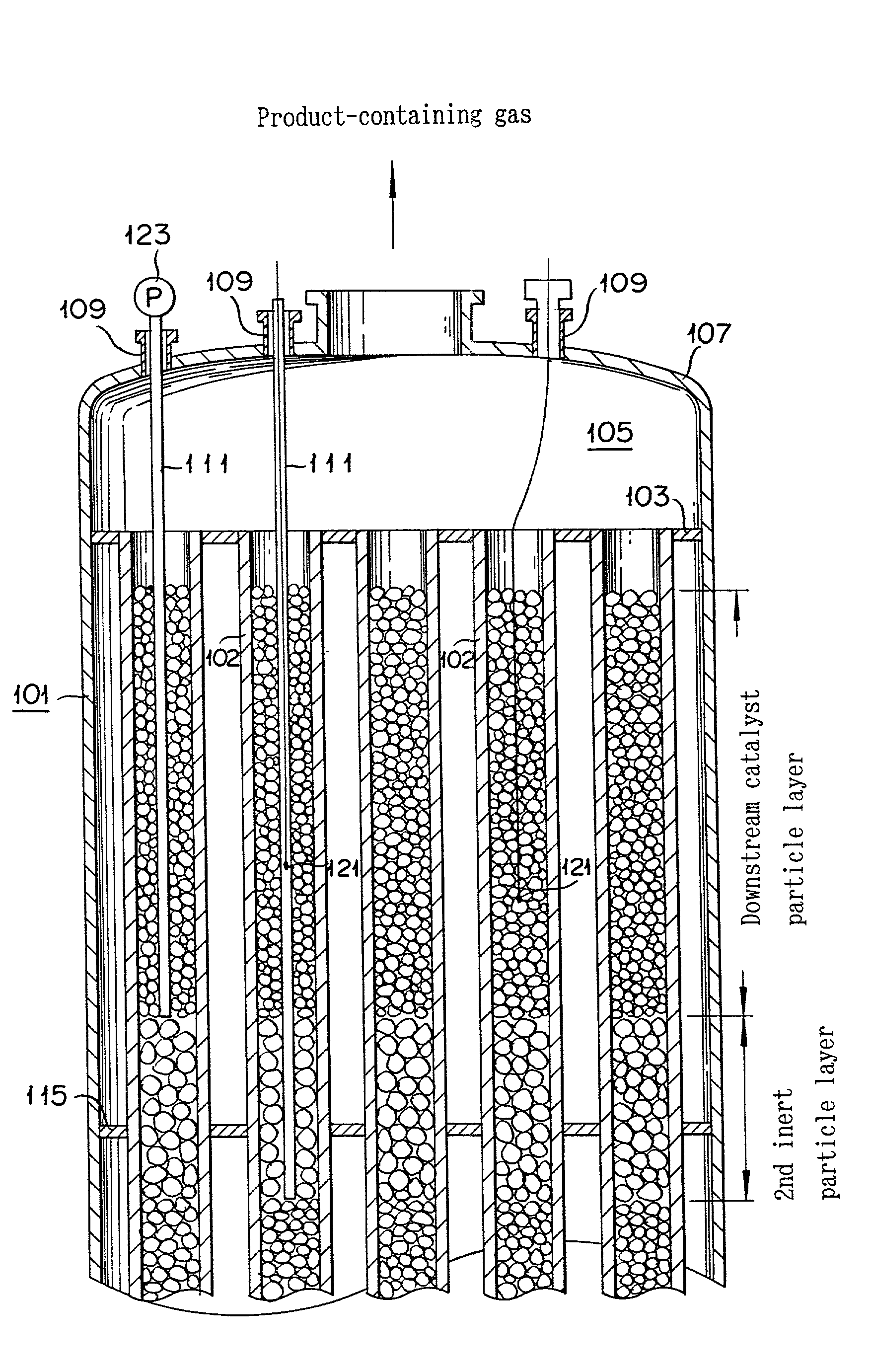
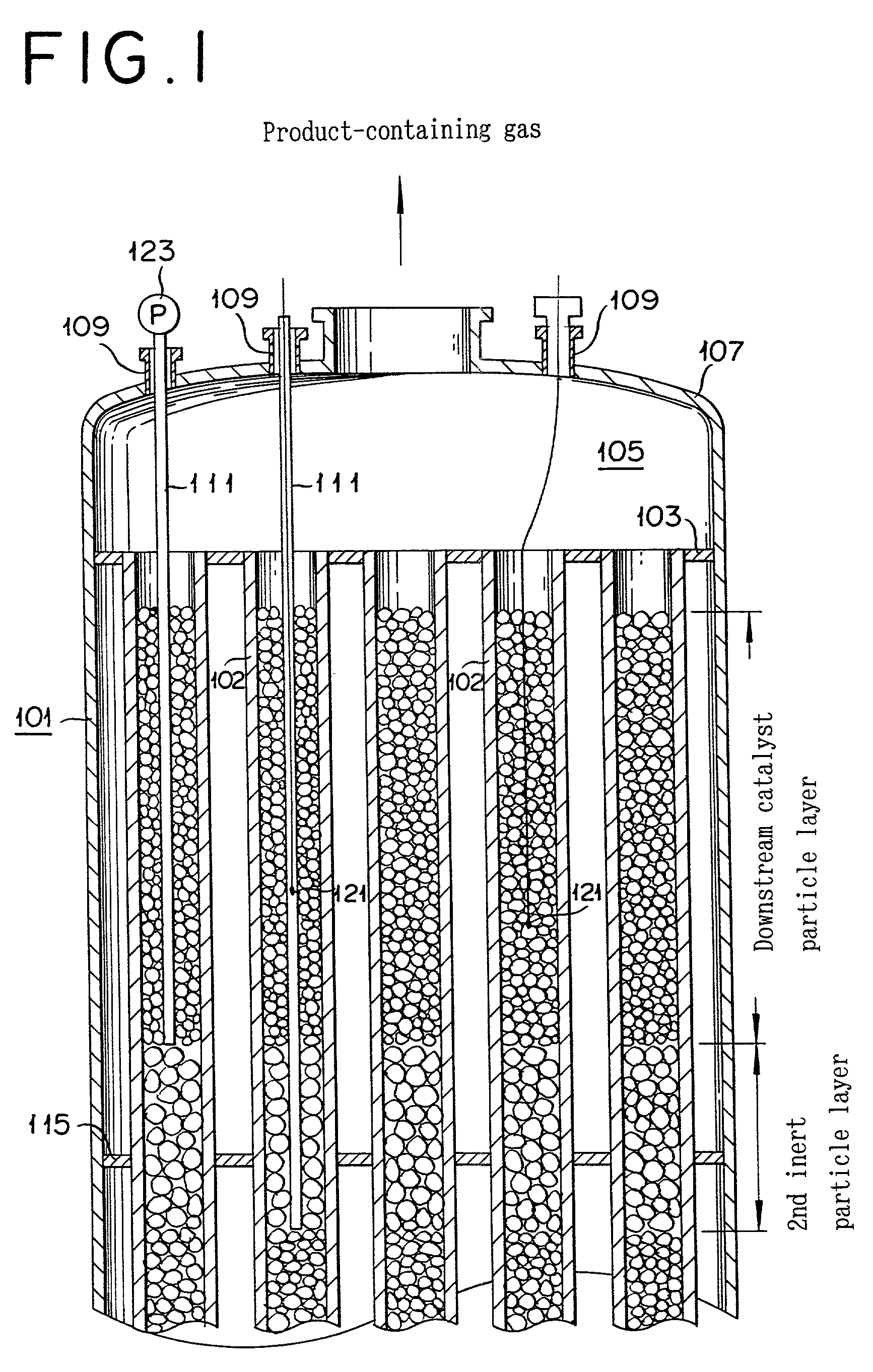
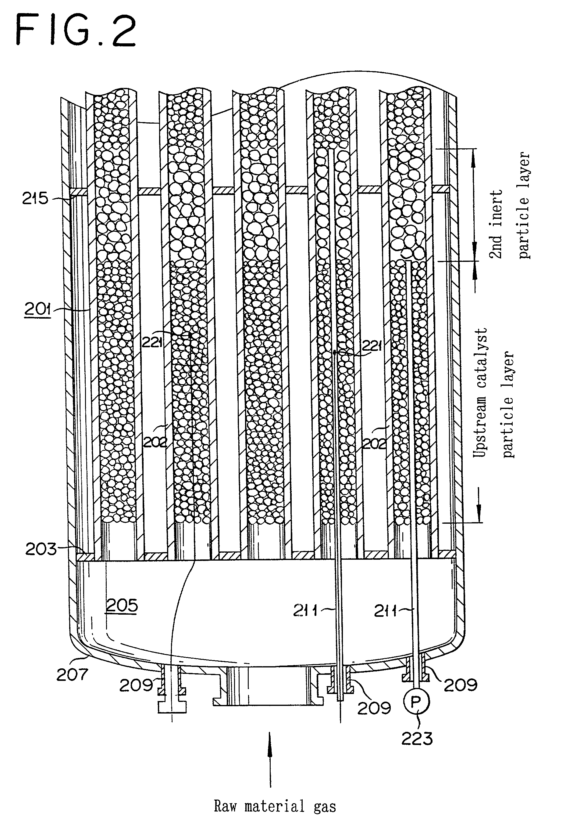
[0109] A vertical shell-and-tube reactor was adopted, having reaction tubes made of steel and of 6,500 mm in length and 25 mm in inside diameter, with an intermediate tube sheet equipped at the middle of the reactor. Upstream catalyst particles, inert particles, and downstream catalyst particles were sequentially filled on the bottom of reaction tubes per each reaction tube as follows:

[0110] Filling Manner

[0111] The upstream catalyst, inert, and downstream catalyst particles were divided into 14 pieces so as to be the same volume, respectively.

[0112] All of non-measuring reaction tubes were filled with the above particles, and then measuring reaction tubes filled therewith in a way that the length of filled layer was the same as the mean of the non-measuring reaction tubes. The volumetric measurement was performed by means of a plastic volumetric measuring vessel. The length of the layer was performed with a measure. The pressure drop of the solid particle layer was measured on a di...


PUM

PropertyMeasurementUnit
lengthaaaaaaaaaa
lengthaaaaaaaaaa
sizeaaaaaaaaaa

Abstract

A shell-and tube reactor including at least one reaction tube with a measuring means, substantially same solid particles being filled in the reaction tubes with or without the measuring means, a length of the filled solid particle layer, and a pressure drop thereof while passing a gas through the reaction tube, per each reaction tube, being substantially the same, respectively. By measuring the temperature of the catalyst particle layer, such a temperature as a representative can be gasped.

Description

[0001] 1. Field of the Invention[0002] The present invention relates to a shell-and-tube heat exchanger type reactor filled with solid particles, and a method for producing (meth) acrylic acid and / or (meth) acrolein with the reactor.[0003] 2. Description of Related Art[0004] Exothermic reactions such as an oxidation reaction in an industrial scale are performed with shell-and-tube reactors filled with catalyst and inert particles. Here, a heat medium exists among the reaction tubes in the shell. Such a reactor is used in the field of chemical industry for example methods for producing phthalic an hydride from o-xylene, acrolein and / or acrylic acid from propylene or propane, and methacrolein and / or methacrylic acid from isobutylene.[0005] Any evaluation of conditions of the shell-and tube reactor filled with catalyst particles, the selectivity and conversion of the prescribed products is affected remarkably by the temperature along with the reaction tubes. This temperature profile al...

Claims


Application Information

Patent Timeline
Patent Type & Authority Applications(United States)
IPC IPC(8): B01J8/00B01J8/06B01J19/00C07B61/00C07C27/14C07C45/35C07C47/22C07C51/25C07C57/05
CPCB01J8/001B01J8/067B01J2208/00044B01J2208/00061B01J2219/00777B01J2208/00513B01J2208/00539B01J2208/021B01J2208/025B01J2208/00212B01J8/06
Inventor MATSUMOTO, YUKIHIRONISHIMURA, TAKESHINAKAHARA, SEIKASAYA, NAOTO
Owner NIPPON SHOKUBAI CO LTD
Why Eureka
Try Eureka