While this is one example, in
casting,
process conditions considerably vary depending on additive
alloy components, and in some cases, there is a case that a production is impossible.
However, a part of the gas remains without release to produce
blisters in the material, where the low-melting-point
metal moves.
Even after the rolling-bonding of the sintered material to the steel strip in a subsequent process, there has been often observed a phenomenon that collapsed
blisters under a rolling-bonding pressure become material defects due to segregation of the low-melting-point
metal at the collapsed
blisters.
In particular, a number of such material defects occur in spring and summer seasons characterized by high temperature and
high humidity which are weather characteristics of Japan.
In a sliding bearing with such material defects (i.e. blisters), contrary to the required bearing performance, when using a bearing, there have been often occurred unfavorable accidents such as
delamination of material, abnormal wear and seizure at blisters.
On the other hand, supposed that only the sliding layer (the second
powder layer) is bonded to the steel strip, the attempt of the press-forming (
powder compacting) of only the second powder in a rolling
machine for powder compacting will fail to keep a continuous strip form by powder compacting in the case of only the second powder consisting of a hard and less ductile aluminum-base powder.
On the other hand, when the amount proportion exceeds 5
mass %, the
bonding strength at the contact interface is deteriorated due to concentration of the low-melting-point metals at the contact interface between the steel and the bonding layer when rolling-bonding of the sintered composite strip to the steel strip by a rolling
machine, or in a subsequent heat treatment process.
A primary cause of the phenomenon of blister occurrence in the conventional materials is that, at the
sintering step before the rolling-bonding of the sintered composite strip to the steel strip, an expansion of the sliding layer occurs at the position near to the bonding layer through which gases are difficult to release and then the expansion pushes the bonding layer to lift up the surface of the bonding layer.
Moreover, with the elevation of the temperature, the aluminum base in the powder particles becomes soft and expansion of the sintered material tends to occur.
The
load carrying capacity of a sliding bearing mainly depends on the
load carrying capacity of the sliding layer which is a top layer but is also affected to a large extent by the fatigue strength of the bonding layer which is a base layer.
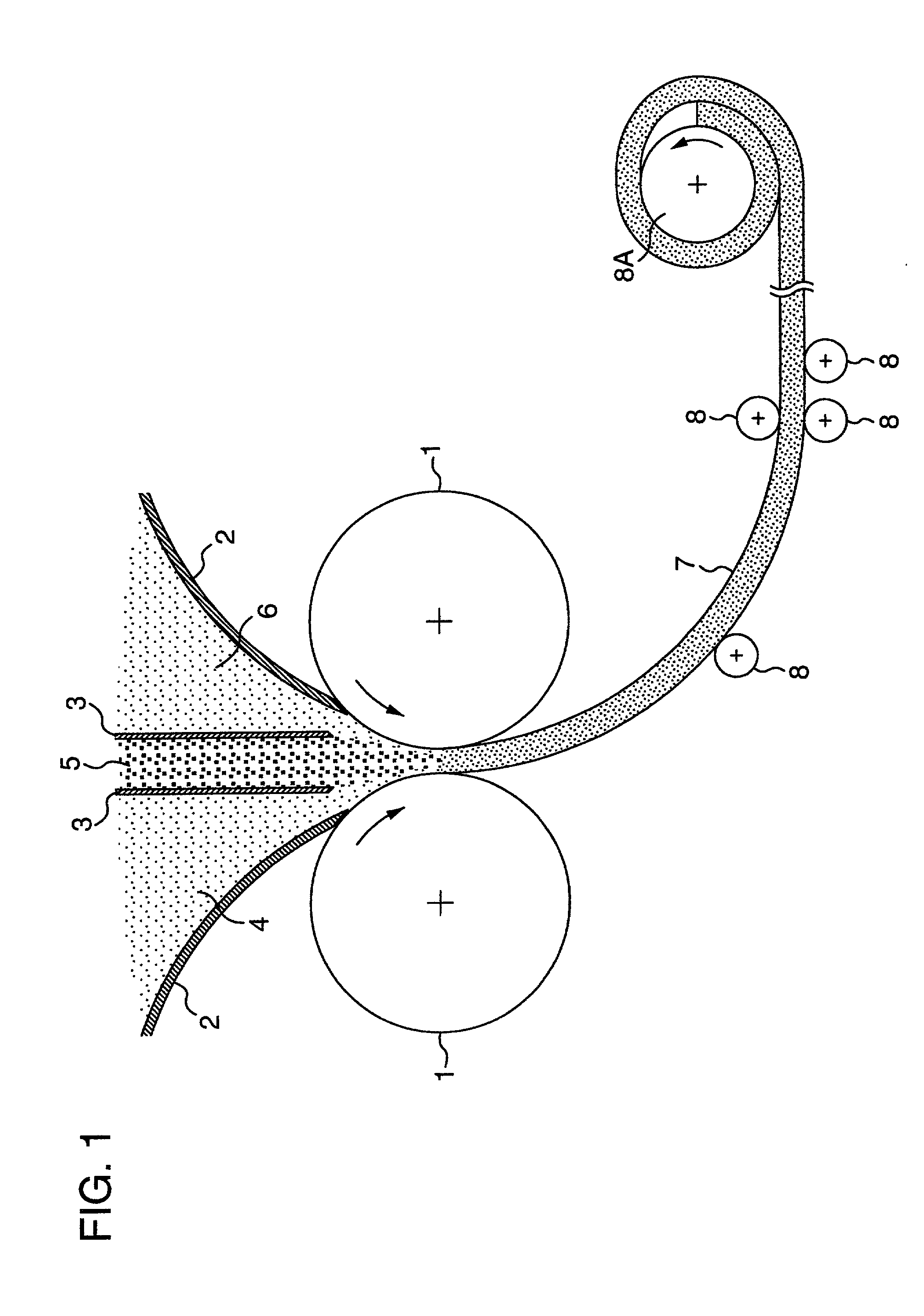
(1) When a composite strip of compacted powders is subjected to powder compacting in a rolling machine for powder compacting, the sacrificial layer and the bonding layer of a hard and not ductile material cannot maintain the shape at the powder compacting by rolling with holding the sliding layer with soft aluminum alloys at both sides of the layer.
Moreover, (2) at the rolling-bonding of the sintered composite strip to the steel strip (back metal) in a later step, the elongation of the bonding layer adjacent to the steel strip is insufficient to result in a weak bonding, or in some case, part of the sintered composite strip peels off the steel strip after the rolling-bonding.
At that time, when the elongation of the bonding layer material is insufficient, material breakage occurs at the rolling-bonding and thus, the bonding becomes impossible.
When the amount exceeds 1 mass %, the production of the aluminum-base
composite material becomes difficult for the above reasons.
Moreover, in the case that the mixing amount of the first element group exceeds 20 mass %, a lot of sweats (a sweaty state) occur on the surfaces of the sacrificial layer and bonding layer sides at obtaining the sintered composite strip by
sintering the composite strip of compacted powders, and thus, the operation of removing the sweats becomes difficult.
When the amount exceeds 8 mass %, the material becomes hard and brittle, which invites deterioration of
foreign matter embeddability and
impact resistance at the time when
foreign matter enters the sliding surface, and further, the material (sliding layer) becomes susceptible to fracture at the rolling-bonding of the sintered composite strip to the steel strip (back metal).
When the amount of the third element group exceeds 2 mass %, the production becomes difficult owing to the occurrence of breakage and crack of the sintered material at the powder compacting by rolling and the rolling-bonding of the sintered composite strip to the steel strip (back metal) as well as the material becomes hard and brittle similar to the case of the second element group, and thereby, deterioration of
foreign matter embeddability and
impact resistance is invited at the time when foreign matter enters the sliding surface.
When the amount of the first element group is less than 0.4 mass %, the effect of
gas release is not achieved as in the bonding layer, and thus a number of blisters occur on the surface after sintering.
However, at the press-forming of the multi-layered body having a three
layers structure consisting of the first to third powders in a rolling machine for powder compacting, the sacrificial layer is unavoidably mixed into the sliding layer to some extent.
At that time, when the
heating temperature is lower than 460.degree. C., the sintering is not realized, and when the temperature exceeds 550.degree. C., the shape of the composite strip cannot be maintained.
As the
reduction rate of the sintered composite strip is increased, the formed area of the fresh surface increases and better bonding between two materials is achieved, but when the
reduction rate is 65% or more, the elongation of the aluminum-base sintered composite strip does not follow and thus, a breakage of the material is invited.
On the other hand, when the
reduction rate of the steel strip is increased, a precision at bending
processing for imparting a curved shape to the product becomes difficult to secure.
When the temperature is lower than 250.degree. C., the
processing strain cannot be removed, while when the material is heated at a temperature exceeding 400.degree. C., the effect of removing the strain is not improved and the bonding of the aluminum-base sintered material layer to the steel strip is rather decreased because the low-melting-point metals seep out as sweats onto the interface between the aluminum-base sintered material layer and the steel strip, whereby the production of the aluminum-base sintered
composite material becomes difficult.
When the treating temperature is lower than 400.degree. C. and the
holding time is less than 0.5 minute, the aluminum-base sintered material layer does not hardened and the strength is not enhanced, so that no improvement in
wear resistance property and anti-seizure property is observed.
When the temperature is higher than 510.degree. C. and the
holding time exceeds 10 minutes, an iron-aluminum metallic compound is formed at the interface between the sintered composite strip and the steel strip and the material becomes brittle, so that the aluminum-base sintered material layer tends to peel off at the
actual use as a bearing.

