
Process for removing hydrogen sulfide from gas streams which include or are supplemented with sulfur dioxide, by scrubbing with a nonaqueous sorbent

a technology of hydrogen sulfide and gas stream, which is applied in the direction of hydrogen sulfide, sulfur preparation/purification, separation processes, etc., can solve the problems of sluggish sulfur formation kinetics, difficult separation and handling, and difficult to deal with solid sulfur products, etc., to achieve simple and inexpensive pumping methods.

Inactive Publication Date: 2003-01-30
URS
View PDF0 Cites 9 Cited by
  • Summary
  • Abstract
  • Description
  • Claims
  • Application Information

AI Technical Summary

Benefits of technology

This approach achieves better H2S removal efficiency, lower amine degradation rates, and reduced byproduct formation, enabling stable operation and efficient sulfur recovery with minimal environmental impact.

Problems solved by technology

One of the main problems with such processes is dealing with the solid sulfur product, which is formed in an uncontrolled manner.
The sulfur formed from aqueous solution is notorious for plugging the absorber or other vessels which it passes through, and it is generally hard to separate and handle.
However, most nonaqueous redox systems have certain disadvantages such as sluggish sulfur formation kinetics or difficulties in regenerating the sorbent with air.
In aqueous systems, contact of polysulfides with air primarily produces sulfates and other undesired sulfur oxyanion byproducts which are difficult to purge from the system.
Under the proper chemical and physical conditions, the efficiencies for simple air regeneration are unexpectedly high and the rates of the air oxidation reaction to sulfur are unexpectedly fast for a nonaqueous system.
The equilibria are such that at low inlet H.sub.2S concentrations it becomes difficult to achieve high H.sub.2S removals at acceptably low liquid flow rates due to the "back-pressure" of H.sub.2S.

Method used


Image

  • Process for removing hydrogen sulfide from gas streams which include or are supplemented with sulfur dioxide, by scrubbing with a nonaqueous sorbent
  • Process for removing hydrogen sulfide from gas streams which include or are supplemented with sulfur dioxide, by scrubbing with a nonaqueous sorbent
  • Process for removing hydrogen sulfide from gas streams which include or are supplemented with sulfur dioxide, by scrubbing with a nonaqueous sorbent

Examples


example 1

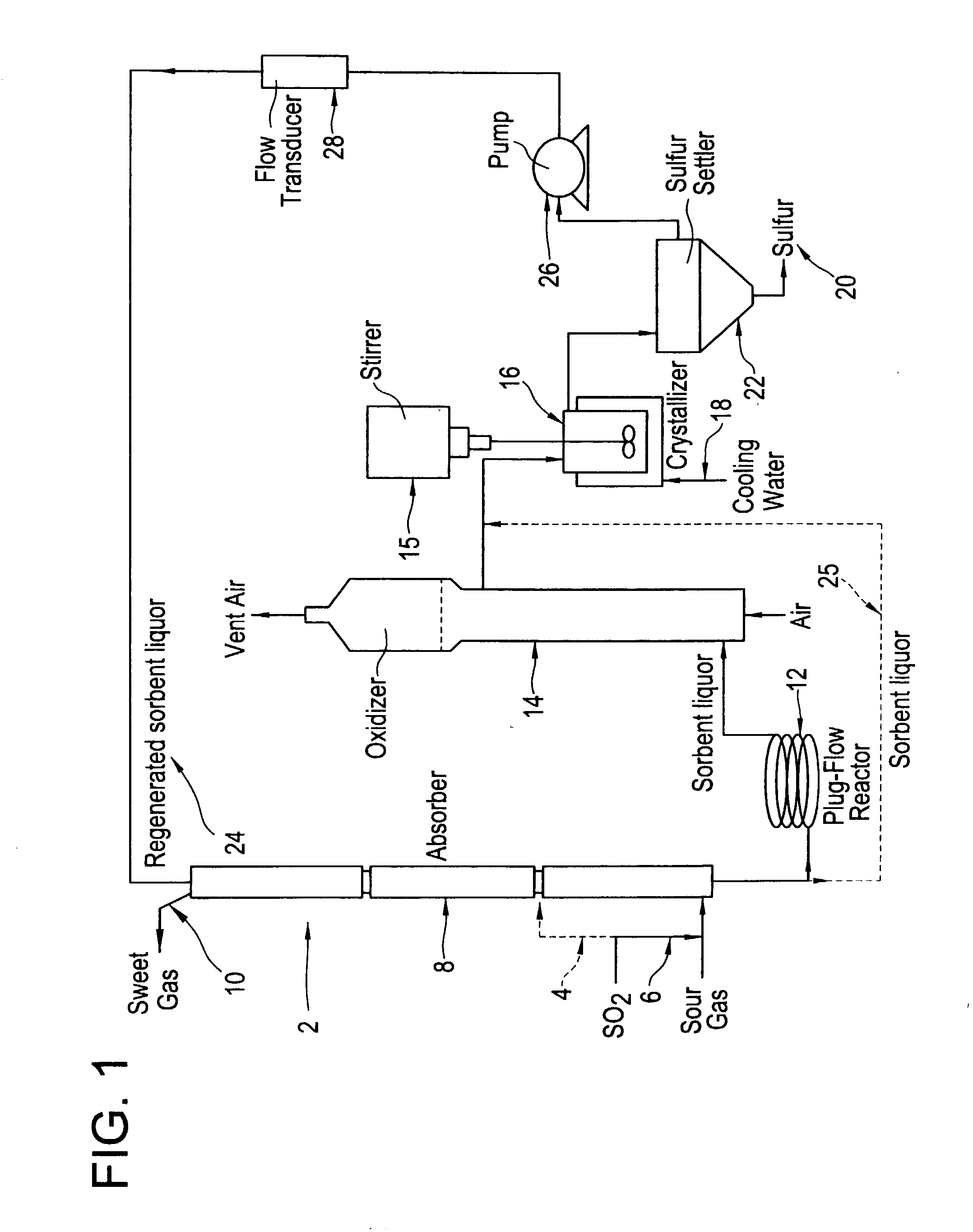
[0050] A long term (44 hour) run was done under typical SANS process operating conditions except with the addition of SO.sub.2. The average inlet H.sub.2S concentration was 32.9% and the average inlet SO.sub.2 concentration was 10%, producing a total S gas content of 42.9%. The total gas flow rate was 350 cc / min. The liquid flow rate was 55 cc / min, and the average liquid inventory was 4000 mL. These conditions were maintained for 44 hours, during which time the average H.sub.2S removal was 99.7%. This average removal is significantly better than that observed in a number of other runs done with 42.9% inlet H.sub.2S but no SO.sub.2, for which the usual average removal is about 95%. During this run the sulfur oxyanion byproduct make rate was 1.92% (total moles sulfur in oxyanion byproducts per mole sulfur absorbed). The major sulfur oxyanion was sulfate. No other peaks which could have indicated other anionic byproducts were seen in the ion chromatograms used to analyze for sulfate an...

example 2

[0052] For this run, the inlet concentration of H.sub.2S to the absorber was reduced from its normal value of 42.9% to 21.5% and the liquid flow rate was also reduced by approximately a factor of two from 55 cc / min to 25 cc / min, with no SO.sub.2 added to the system. This produced conditions in which the removal of H.sub.2S by the SANS sorbent is approaching equilibrium control and as a consequence the H.sub.2S removal was only 64%. At this point, adding 2.0% SO.sub.2 to the gas stream and maintaining the same total sulfur concentration in the gas produced an H.sub.2S removal of 72%. Similarly, adding 4.0% SO.sub.2 increased the H.sub.2S removal to 80%, and adding 6.0% SO.sub.2 gave a removal of 90% of the H.sub.2S. At this point, when the SO.sub.2 flow was turned off (without increasing the H.sub.2S inlet to compensate), the H.sub.2S removal decreased to a value of 59.4%, consistent with the low removal noted before starting SO.sub.2 flow, adjusted for the somewhat lower H.sub.2S co...

example 3

[0053] To determine if the direct reaction of H.sub.2S with SO.sub.2 occurs to an appreciable extent in this system, the bench scale unit was run under similar conditions to those in Example 2 except that the initial sorbent did not contain any elemental sulfur. At an average inlet H.sub.2S concentration of 22%, SO.sub.2 concentration of 6%, and liquid flow rate of 25 mL / min, the outlet H.sub.2S concentration was initially 10%, a removal of only 52%.

[0054] The removal improved somewhat with time, probably due to the formation of some elemental sulfur either by the direct reaction of H.sub.2S with SO.sub.2 or by air oxidation of sulfide in the oxidizer. Clearly, however, the direct reaction of H.sub.2S with SO.sub.2 is not as facile as the reaction mediated by elemental sulfur, which evidently proceeds via the intermediate polysulfide formed by reaction of H.sub.2S and S.sub.8 in solution.


PUM

PropertyMeasurementUnit
temperatureaaaaaaaaaa

Abstract

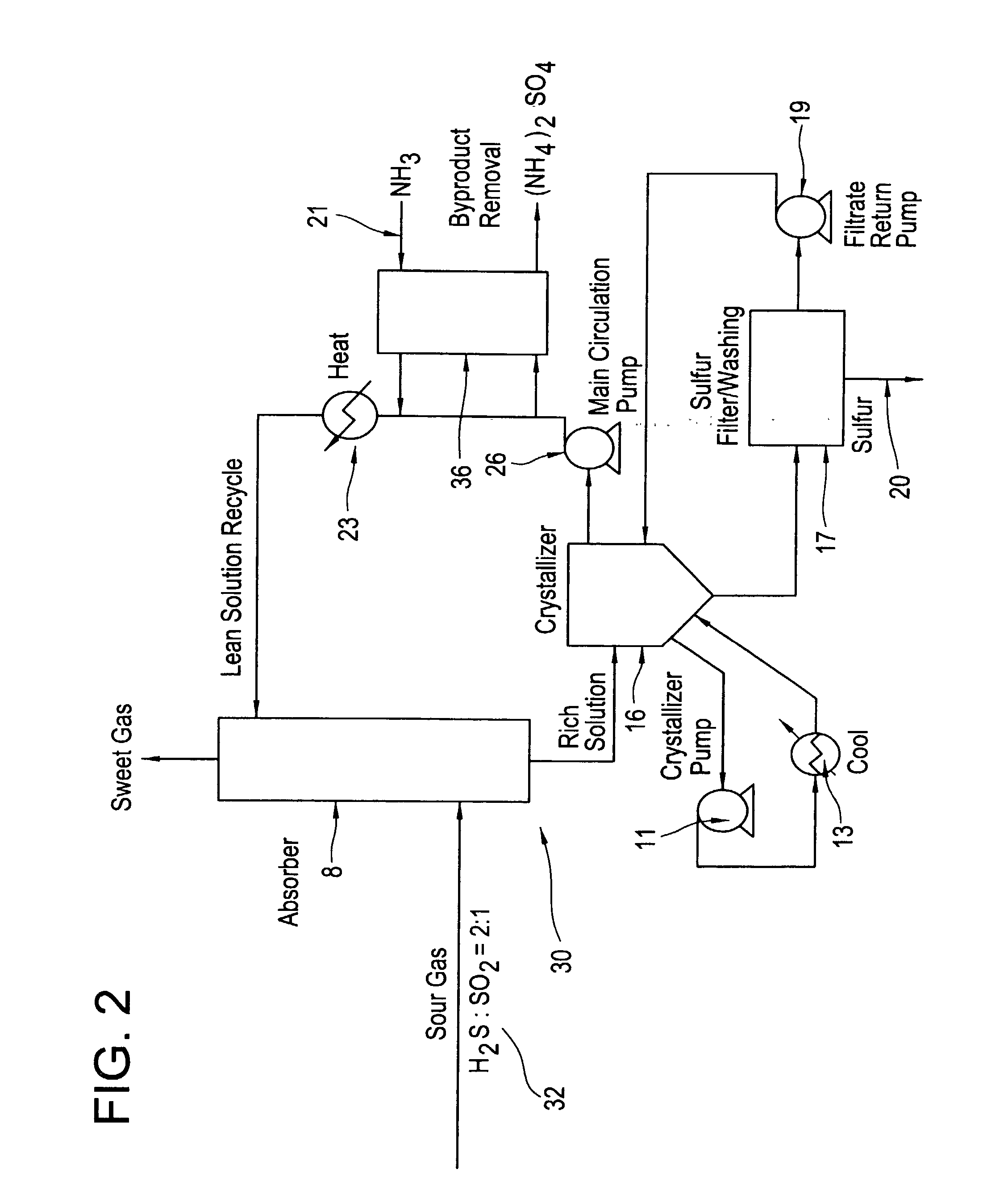
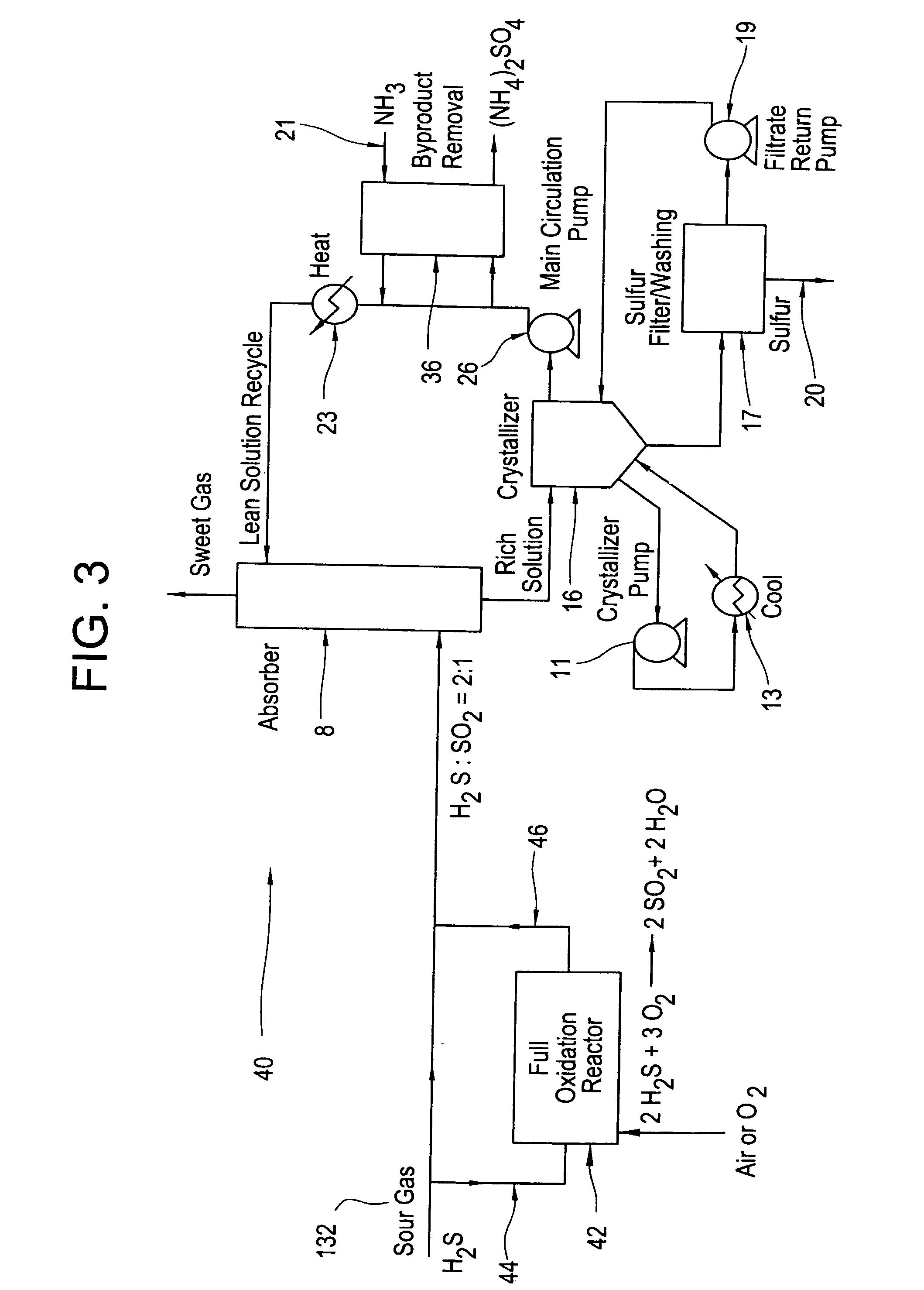
The invention relates to improvements in a known process and system wherein hydrogen sulfide is removed from a gaseous stream, using a nonaqueous scrubbing liquor in which are dissolved sulfur and a reaction-promoting amine base. In a first aspect of the invention sulfur dioxide is added to the sulfur-amine nonaqueous sorbent (or advantage is taken of SO2 which may already be present in the gas stream) to obtain better H2S removal, lower chemical degradation rates, and lower rates of formation of byproduct sulfur salts. In a further aspect of the invention the gas to be treated is mixed with oxygen and passed through an oxidation catalyst reactor to either effect oxidation of part of the H2S to form the required amount SO2 for reaction with the remaining H2S, or to effect partial oxidation of the H2S in the feed gas to form elemental sulfur, or to form various combinations of products as desired for the application, prior to scrubbing with the nonaqueous solvent.

Description

[0001] This application is a continuation-in-part of copending application Ser. No. 09 / 503,898, filed Feb. 15, 2000.[0002] This invention relates generally to processes and systems for removing hydrogen sulfide from a gaseous stream. More specifically the invention relates to improvements in a known process and system wherein hydrogen sulfide is removed from a gaseous stream, using a nonaqueous scrubbing liquor in which are dissolved sulfur and a reaction-promoting amine base. In a first aspect of the invention sulfur dioxide is added as an oxidizing gas to the sulfur-amine nonaqueous sorbent (or advantage is taken of SO.sub.2 which may already be present in the gas stream) to obtain better H.sub.2S removal, lower chemical degradation rates, and lower rates of formation of byproduct sulfur salts. In a further aspect of the invention the gas to be treated is mixed with oxygen and passed through an oxidation catalyst reactor to either effect oxidation of part of the H.sub.2S to form t...

Claims


Application Information

Patent Timeline
Patent Type & Authority Applications(United States)
IPC IPC(8): B01D53/14B01D53/52B01D53/73C01B17/05
CPCB01D53/1468B01D53/52B01D53/523B01D53/73C01B17/05
Inventor DEBERRY, DAVID W.DALRYMPLE, DENNISFISHER, KEVIN S.
Owner URS
Features
  • Generate Ideas
  • Intellectual Property
  • Life Sciences
  • Materials
  • Tech Scout
  • Unparalleled Data Quality
  • Higher Quality Content
  • 60% Fewer Hallucinations
Learn More