High rate deposition at low pressures in a small batch reactor

a high-rate deposition and batch reactor technology, applied in conveyor parts, transportation and packaging, coatings, etc., can solve the problems of large differences in the deposition rate from substrate to substrate, non-uniform deposition across the substrate, and inability to heat by convection, so as to increase the rate of material deposition

Inactive Publication Date: 2003-03-13
APPLIED MATERIALS INC
View PDF66 Cites 645 Cited by
  • Summary
  • Abstract
  • Description
  • Claims
  • Application Information

AI Technical Summary

Benefits of technology

[0009] It is therefore an object of the present invention to provide a method and apparatus for CVD resulting in an increased rate of uniform deposition of materials on a substrate.
[0010] It is a further object of the present invention to provide a method and apparatus providing more rapid and uniform deposition of material on a substrate in a small batch reactor.
[0011] It is a still further object of the present invention to provide a method and apparatus that results in increased deposition rates and with surface roughness comparable to that obtained only at lower deposition rates in conventional furnace type batch reactors.

Problems solved by technology

Since the substrate is in a low pressure vacuum chamber, heating by convection is not feasible, nor is heating by conduction.
Operation at higher concentrations of the reactant gases results in non-uniform deposition across the substrates and great differences in the deposition rate from substrate to substrate due to gas depletion effects.
Increased flow rates may improve the deposition uniformity at higher pressures, however increased pressures result in gas phase nucleation causing particles to be deposited on the substrates.
A disadvantage of the reactor of FIG. 1 is that increasing reactant gas flow relative to a wafer surface in the reactor of FIG. 1 is problematical.
There are other problems associated with this reactor, such as film deposition on the interior quartz tube 10, which decreases the partial pressure of the reactive feed gas concentrations near the surface of the substrates 13 resulting in reduced deposition rates and potential contamination caused by the film deposited on the tube wall flaking off and depositing on the substrates 13.
Finally, to offset the depletion of the reactive chemical species from the entrance to the exit of this style reactor, a temperature gradient is created across the substrate load zone such that the deposition rate from substrate to substrate is equal, however in the case of polycrystalline silicon deposition, this creates a different problem because the grain size is temperature dependent and the temperature gradient causes the polycrystalline silicon grain size to vary from substrate to substrate.
This variation in grain size from substrate to substrate can cause problems with the subsequent patterning of the polycrystalline silicon, resulting in variations in the electrical performance of the integrated circuits in which the polycrystalline silicon is used.
In addition, uniform temperature control over the substrates is very difficult to maintain, resulting in non-uniform silicon deposition over the substrates 18.
A major problem associated with the reactor in FIG. 3 is the limited throughput (i.e. the number of substrates processed per hour) as compared to a batch reactor.
This problem can be addressed by increasing the operating pressure to 10 Torr or greater, resulting in high deposition rates exceeding 1000 angstroms per minute, however operating the reactor at such high pressures can result in a gas phase reaction where silicon particles are formed in the gas and deposit on the substrate as particles.
Also, deposition at high pressures changes the grain structure of the polysilicon.
Another problem associated with the reactor is the tendency for silicon to be deposited on the quartz walls 33, 34 resulting in loss of radiant energy transmission from the lamps 31 causing non-uniform heating of the substrate and resulting in non-uniform film deposition on the substrate 28.
The forceful gas flow avoids gas depletion effects, thins the boundary layer and results in faster delivery of reactants to substrate surfaces, resulting in surface rate reaction limited operation.
In-situ cleans generally reduces system down-time since the system would otherwise have to be wet-cleaned which is a laborious and tedious process.

Method used


Image

  • High rate deposition at low pressures in a small batch reactor
  • High rate deposition at low pressures in a small batch reactor
  • High rate deposition at low pressures in a small batch reactor

Examples


Embodiment Construction

[0069] A preferred embodiment of the method of the present invention will now be described in reference to FIG. 4. The term silicon deposition or silicon used in this disclosure is used as a generic term to include polycrystalline silicon, amorphous silicon, and epitaxial silicon, with or without doping. Other materials deposited by CVD are also included in the present invention, such as silicon nitride, silicon oxides, tungsten, tungsten silicide, high-k dielectrics and other materials in which the deposition rate is enhanced by across the wafer gas flow.

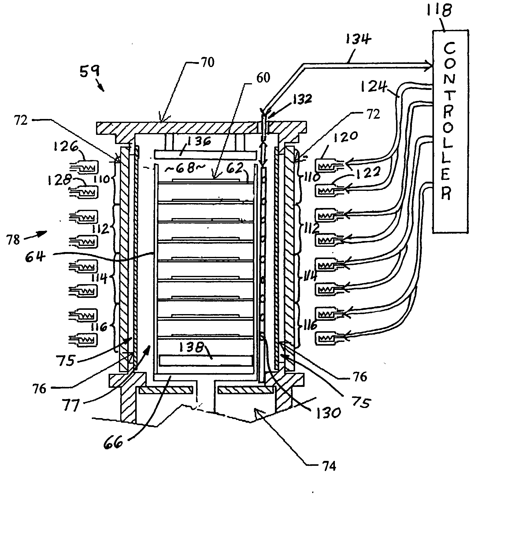
[0070] In the particular case of the deposition of polycrystalline silicon, the process begins by placing a plurality of wafers on a multi-wafer carrier / boat 48. The boat with the wafers is placed in the process chamber 50 and rotated 52 and heated 54, with the wafers being heated as uniformly as possible. The preferred temperature range for silicon deposition is 500.degree. C.-900.degree. C. with a most preferred range of 600.degr...


PUM

PropertyMeasurementUnit
speedaaaaaaaaaa
gas pressureaaaaaaaaaa
pressureaaaaaaaaaa

Abstract

A chemical vapor deposition reactor including a wafer boat with a vertical stack of horizontally oriented susceptors serving as thermal plates and each having pins extending upward for suspending a wafer between a pair of susceptors. Reactant gas injector and exhaust apparatus are positioned to concentrate a forceful supply of reactant gas across each wafer at a speed in excess of 10 cm / sec. The pressure is held in the range of 0.1 to 5,000 mTorr. The forceful gas flow avoids gas depletion effects, thinning the boundary layer and resulting in faster delivery of reactants to substrate surfaces, resulting in surface rate reaction limited operation. A plurality of individually controllable heaters are spaced vertically around the sides of the boat. Temperature sensors monitor the temperature along the boat height and provide input to a controller for adjusting the heater drive to optimize the temperature uniformity.

Description

[0001] This application is a continuation in part of (a) U.S. application Ser. No. 09 / 954,705 filed Sep. 10, 2001 which is a continuation in part of U.S. application Ser. No. 09 / 396,588 (U.S. Pat. No. 6,287,635) filed Sep. 15, 1999 (which claims the benefit of U.S. Provisional Application Serial No. 60 / 100,594 filed Sep. 16, 1998), which is a continuation in part of (i) U.S. application Ser. No. 08 / 909,461 (U.S. Pat. No. 6,352,593) filed Aug. 11, 1997, (ii) U.S. application Ser. No. 09 / 228,835 (U.S. Pat. No. 6,167,837) filed Jan. 12, 1999 (which claims the benefit of U.S. Application Serial No. 60 / 071,572 filed Jan. 15, 1998), and (iii) U.S. application Ser. No. 09 / 228,840 (U.S. Pat. No. 6,321,680) filed Jan. 12, 1999 (which claims the benefit of U.S. Provisional Application Serial No. 60 / 071,571 filed Jan. 15, 1998); and (b) U.S. application Ser. No. 09 / 396,590 filed Sep. 15, 1999 (which claims priority from U.S. Application Serial No. 60 / 100,596 filed Sep. 16, 1998). The disclosur...

Claims


Application Information

Patent Timeline
Patent Type & Authority Applications(United States)
IPC IPC(8): C23C16/24C23C16/34C23C16/44C23C16/455C23C16/458C23C16/46C23C16/48C23C16/509C23C16/54H01J37/32H01L21/00H01L21/205H01L21/318H01L21/677
CPCC23C16/24C23C16/345C23C16/4405C23C16/4412C23C16/45502C23C16/4557C23C16/45572C23C16/45574C23C16/4584C23C16/46C23C16/481H01J37/32082H01J37/32733H01J2237/2001H01L21/3185H01L21/67017H01L21/67069H01L21/67115H01L21/67754H01L21/67757H01L21/02381H01L21/02532H01L21/0262H01L21/02661H01L21/0217
Inventor COOK, ROBERT C.BRORS, DANIEL L.MITCHENER, JAMESORMONDE, GABE A.
Owner APPLIED MATERIALS INC
Why Eureka
Try Eureka