Method of manufacturing magnet material, ribbon-shaped magnet material, magnetic powder and bonded magnet

a technology of ribbon-shaped magnets and manufacturing methods, which is applied in the manufacture of magnetic materials, magnetic bodies, inductance/transformers/magnets, etc., can solve the problems of large amount of melt spun ribbon, insufficient magnetic properties of bonded magnets manufactured by using these magnetic powders, and differences in microstructure, etc., to achieve excellent magnetic properties, high magnetic properties, and relatively high magnetic flux density and coercive force of magnetic powders

Inactive Publication Date: 2003-03-27
ARAI AKIRA +1
View PDF8 Cites 8 Cited by
  • Summary
  • Abstract
  • Description
  • Claims
  • Application Information

AI Technical Summary

Benefits of technology

[0123] In these three molding methods, the extrusion molding and the injection molding (in particular, the injection molding) have advantages in that the latitude of shape selection is broad, the productivity is high, and the like. However, these molding methods require to ensure a sufficiently high fluidity of the compound in the molding machine in order to obtain satisfactory moldability. For this reason, in these methods it is not possible to increase the content of the magnetic powder, namely, to make the bonded magnet having high density, as compared with the case of the compression molding method. In this invention, however, it is possible to obtain a high magnetic flux density as will be described later, so that excellent magnetic properties can be obtained even without making the bonded magnet high density. This advantage of the present invention can also be extended even in the case where bonded magnets are manufactured by the extrusion molding method or the injection molding method.
[0124] The content of the magnetic powder in the bonded magnet is not particularly limited, and it is normally determined by considering the type of the molding method or obtainable moldability and high magnetic properties. More specifically, it is preferable to be in the range of 75-99.5 wt %, and more preferably in the range of 85-98 wt %.
[0125] In particular, in the case of a bonded magnet to be manufactured by the compression molding method, the content of the magnetic powder should preferably lie in the range of 90-99.5 wt %, and more preferably lie in the range of 93-98.5 wt %.
[0126] Further, in the case of a bonded magnet to be manufactured by the extrusion molding or the injection molding, the content of the magnetic powder should preferably lie in the range of 75-98 wt %, and more preferably lie in the range of 85-97 wt %.
[0127] Further, in the present invention, it is also possible to provide a bonded magnet having elasticity (flexibility) by using a binder having elasticity. As for such a binder, various rubbers and various thermoplastic elastomers can be used. Examples of the various rubbers include olefin-based rubbers such as natural rubber (NR), polyisoprene rubber (IR), butadiene based rubber such as butadien rubber (BR, 1, 2-BR), styrene-butadiene rubber (SBR) and the like, diene-based rubber such as chloroprene rubber (CR) and acrylonitorile butadiene rubber (NBR) and the like, isobutylene-isoprene rubber (IIR), ethylene-propylene rubber (EPM, EPDM), ethylene-vinylacetate rubber (EVA), acrylic rubber (ACM, ANM), halogenated isobutylene-isoprene rubber (X-IIR); urethane based rubber such as polyester urethane rubber (AU) and polyether urethane rubber (EU); ether-based rubber such as hydrin rubber (CO, ECO, GCO, EGCO; polysulfide-based rubber such as polysulfide rubber (T); silicone rubber (Q); fluorocarbon rubber (FKM, FZ); and chlorinated polyethylene (CM). Further, examples of the thermoplastic elastomers include styrene-based elastomer, polyolefin thermoplastic elastomer; polyvinyl choride thermoplastic elastomer, thermoplastic polyurethane elastomer, polyester thermoplastic elastomer, polyamide thermoplastic elastomer, thermoplastic 1,2-polybutadiene, thermoplastic trans-polyisoprene elastomer, fluorocarbon thermoplastic elastomer, and chrolinated polyethylene elastomer, and the like.
[0128] The density .rho. of the bonded magnet is determined by factors such as the specific gravity of the magnetic powder contained in the magnet, the content of the magnetic powder, the void ratio of the bonded magnet and the like. In the bonded magnets according to this invention, the density .rho. is not particularly limited, but it is preferable that the density .rho. is equal to or greater than 5.0 g / cm.sup.3, and it is more preferable that the density .rho. is in the range of 5.5-6.6 g / cm.sup.3. Further, in the case of the bonded magnet having elasticity, the density .rho. may not be greater than 5.0 g / cm.sup.3.

Problems solved by technology

However, the peripheral surface of the cooling roll is usually formed of a metal having high heat conductivity, so that the difference in the microstructure (difference in the crystal grain diameter) between the roll contact surface (surface making contact with the peripheral surface of the cooling roll) and the free surface (surface opposite to the roll contact surface) of the obtained melt spun ribbon is large due to the difference in the cooling rate.
Because of this, when magnetic powder is obtained by milling the ribbon, their magnetic properties are dispersed from one magnetic powder to another, and hence the bonded magnets manufactured by using these magnetic powders do not have satisfactory magnetic properties.
On the other hand, if the thickness of the surface layer 52 is too large, there is a possibility of developing cracks or peeling in the surface layer 52 due to thermal shock when the number of times of use gets large.
In particular, if the thickness of the surface layer 52 is extremely large, the cooling capability is reduced, so that there is shown an overall tendency of coarsening of the crystal grain diameter, which leads to the possibility that a sufficient improvement in the magnetic properties may not be achieved.
As a result, when the contact time described later is relatively small, the overall heat transfer becomes poor, so that the magnetic properties are deteriorated.
As a result, especially in continuous production, the crystal grain diameter coarsens with the lapse of the time, and stable production of the melt spun ribbon with high magnetic properties becomes difficult.
On the other hand, if the radius of the cooling roll 5 is too large, machining of the cooling roll itself tends to be poor, becoming difficult in some cases.
Further, such a cooling roll results in the increase in the scale of the device.
In either case, sufficient enhancement in the magnetic properties cannot be attained even if a heat treatment would be carried out at a later time.
As a result, the size of crystal grains on the free surface 82 side becomes large, so that sufficient magnetic properties cannot be obtained even if a heat treatment is given later on.
If the thickness t is too small, the occupation rate of the amorphous structure increases which prevents sufficient enhancement of the magnetic properties even with a later heat treatment.
In addition, productivity per unit time is deteriorated.
This is because sufficient enhancement of the magnetic properties, in particular the coercive force and the rectangularity cannot be attained if the mean crystal grain diameter is too large.
For this reason, in these methods it is not possible to increase the content of the magnetic powder, namely, to make the bonded magnet having high density, as compared with the case of the compression molding method.
If the coercive force is less than the stated lower limit, demagnetization under application of a reverse magnetic field is conspicuous for some types of motors, and the heat resistance at high temperatures is deteriorated.
Further, if the coercive force exceeds the above-stated upper limit, the magnetizability is deteriorated.

Method used


Image

  • Method of manufacturing magnet material, ribbon-shaped magnet material, magnetic powder and bonded magnet
  • Method of manufacturing magnet material, ribbon-shaped magnet material, magnetic powder and bonded magnet
  • Method of manufacturing magnet material, ribbon-shaped magnet material, magnetic powder and bonded magnet

Examples


embodiment 1

[0133] (Embodiment 1)

[0134] A melt spun ribbon with alloy composition Nd.sub.9.1Fe.sub.balCo.su-b.8.5B.sub.5.5Al.sub.0.2 was obtained according to the following method.

[0135] First, each of the materials Nd, Fe, Co, B and Al was weighed, and then their mixture was melted and cast in an Ar gas in a high frequency induction melting furnace to obtain a mother alloy ingot. Then, a sample of about 15 g was segmented from the ingot.

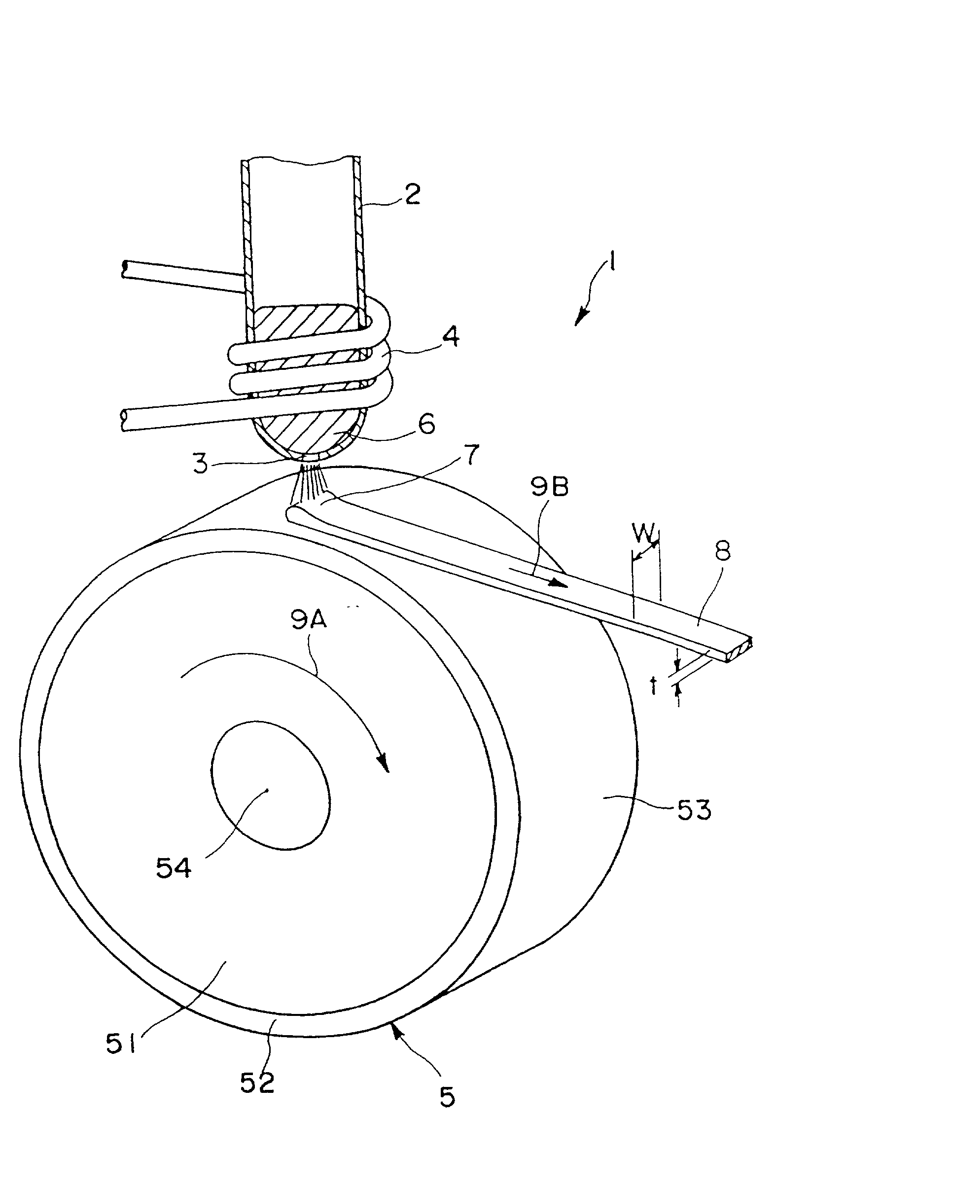
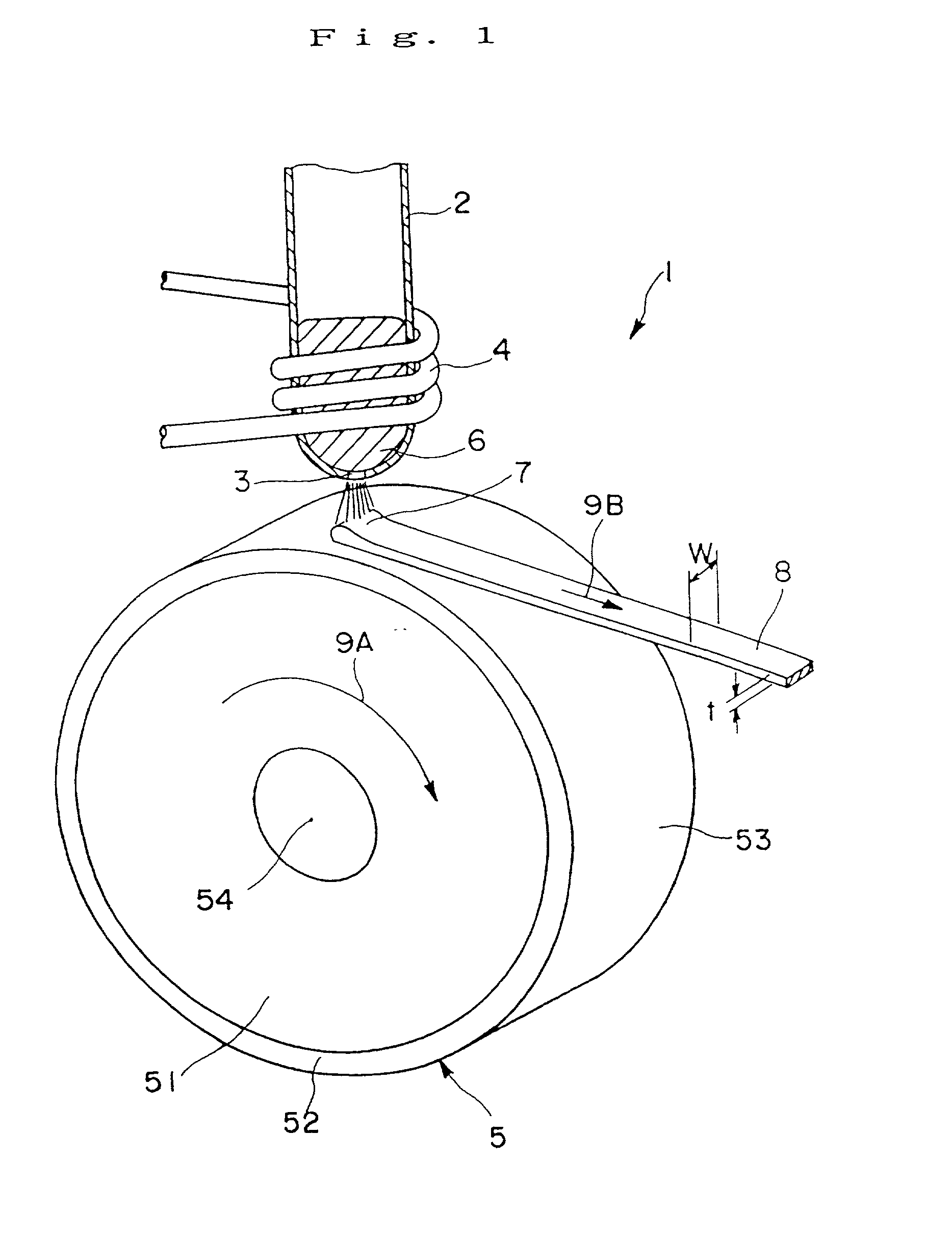
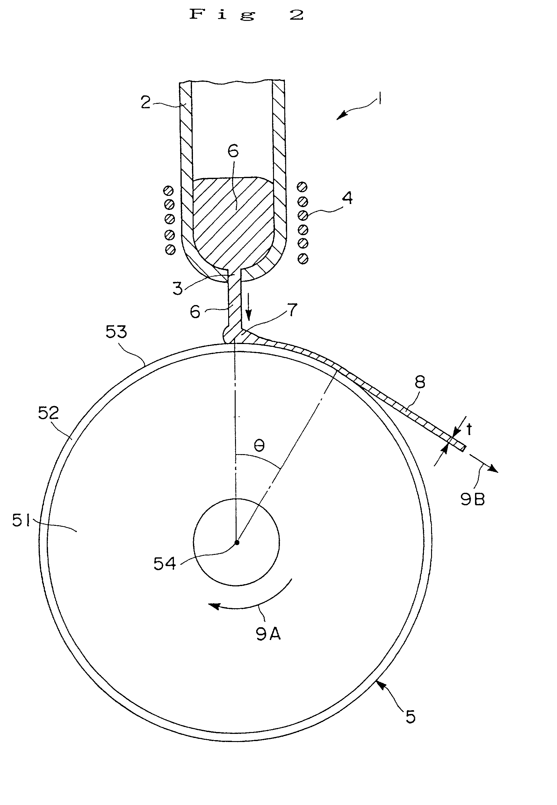
[0136] A melt spinning apparatus 1 as shown in FIG. 1 to FIG. 3 was prepared, and the sample was placed in a quartz tube 2 having a nozzle (a circular orifice having a diameter of 0.6 mm) 3 at the bottom.

[0137] As for the cooling roll 5, a roll (radius 100 mm) provided with the surface layer 52 of ZrC of a mean thickness 5 .mu.m formed by sputtering on the outer periphery of the copper-made base part 51, was manufactured, and the peripheral surface 53 of the cooling roll was finished by surface grinding so as to have a surface roughness Ra of 0.5 .mu.m.

[0138] A...

example 2

[0158] As the cooling roll for the melt spinning apparatus 1, a cooling roll (with radius 120 mm) provided with the surface layer 52 having a constituent material, thickness, and surface roughness Ra shown in Table 1 was manufactured by sputtering on the outer periphery of the copper base part 51. The cooling rolls indicated by the sample Nos. 11 and 12 were respectively provided with laminates of two ceramic layers (layer A and layer B) with different compositions (layer A is the outermost layer and layer B is on the base part 51 side) as their surface layers 52.

[0159] By rotating these cooling rolls at a peripheral velocity of 19 m / s, melt spun ribbons with alloy composition represented by Nd.sub.6.5Pr.sub.1.8Dy.sub.0.7Fe.sub.balCo.sub.7.8B.sub.5.4Si.sub.1.0Al.s-ub.0.2 were manufactured in the same way as in Example 1. The mean thickness t of the obtained melt spun ribbon and the contact time (calculated in the same way as in Example 1) of the melt spun ribbon with the peripheral ...

example 3

[0165] Bonded magnets were manufactured in the same manner as that of Examples 1 and 2 except that the bonded magnets were manufactured by extrusion molding, and then the magnetic properties thereof were measured in the same manner as that of Examples 1 and 2. In this Example, a result similar to the above was obtained.


PUM

PropertyMeasurementUnit
timeaaaaaaaaaa
thicknessaaaaaaaaaa
radiusaaaaaaaaaa

Abstract

A magnet material having excellent magnetic properties and a bonded magnet formed of the magnet material as well as a method of manufacturing the magnet material are disclosed. The method of manufacturing the magnet material is carried out by discharging a molten metal of the magnet material from a nozzle while rotating a cooling roll having a surface layer composed of ceramics on its outer periphery to be collided with the surface layer of the cooling roll and solidified by cooling, the method of manufacturing the magnet material being characterized in that the time during which the magnet material is in contact with the surface layer of the cooling roll is not less than 0.5 ms when the molten metal of said magnet material is discharged from directly above the center of rotation of the cooling roll toward an apex part of the cooling roll to be collided with the apex part.

Description

BACKGROUND OF THE INVNETION[0001] 1. Field of the Invention[0002] This invention relates to a method of manufacturing magnet material, a ribbon-shaped magnet material, magnetic powder and a bonded magnet.[0003] 2. Description of the Prior Art[0004] Bonded magnets formed by binding magnetic powder with a binding resin are used for motors and various kinds of actuators because of the advantages that they have a wide versatility on their shapes.[0005] A magnet material composing a bonded magnet is manufactured, for example, by a quenching method employing a melt spinning apparatus. When the melt spinning apparatus is equipped with a single cooling roll, the method is referred to as a single roll method.[0006] In the single roll method, a magnet material with prescribed alloy composition is melted by heating, the molten metal is jetted from a nozzle, to be collided with the peripheral surface of the cooling roll rotating with respect to the nozzle, and solidified by quenching through co...

Claims


Application Information

Patent Timeline
Patent Type & Authority Applications(United States)
IPC IPC(8): B22F1/00B22F3/00B22D11/06B22F9/08C22C33/02C22C38/00H01F1/00H01F1/057H01F1/06H01F1/08H01F41/02
CPCH01F1/0571H01F1/0578H01F1/00
Inventor ARAI, AKIRAKATO, HIROSHI
Owner ARAI AKIRA
Why Eureka
Try Eureka