Oscillator and electronic apparatus using the same

a technology of oscillator and electronic device, applied in the direction of waveguide type device, high frequency circuit adaptation, semiconductor/solid-state device details, etc., can solve the problems of difficult to reduce positional shift, difficult to reduce deviations in oscillating frequency, and difficult to make the oscillator low or compa

Inactive Publication Date: 2003-06-12
MURATA MFG CO LTD
View PDF0 Cites 12 Cited by
  • Summary
  • Abstract
  • Description
  • Claims
  • Application Information

AI Technical Summary

Problems solved by technology

Sho-63-9203, however, since the dielectric resonator is placed on the dielectric substrate, it is very difficult to reduce positional shifts between the dielectric resonator and the microstrip line formed on the dielectric substrate, and it is also very difficult to reduce deviations in the oscillating frequency.
It is difficult to

Method used


Image

  • Oscillator and electronic apparatus using the same
  • Oscillator and electronic apparatus using the same
  • Oscillator and electronic apparatus using the same

Examples


Embodiment Construction

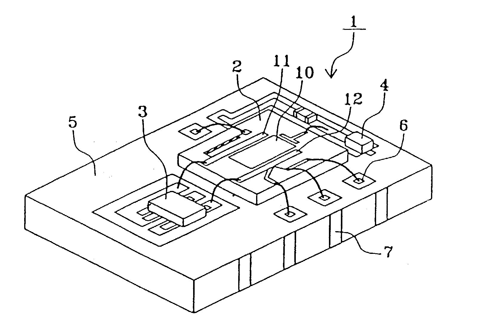
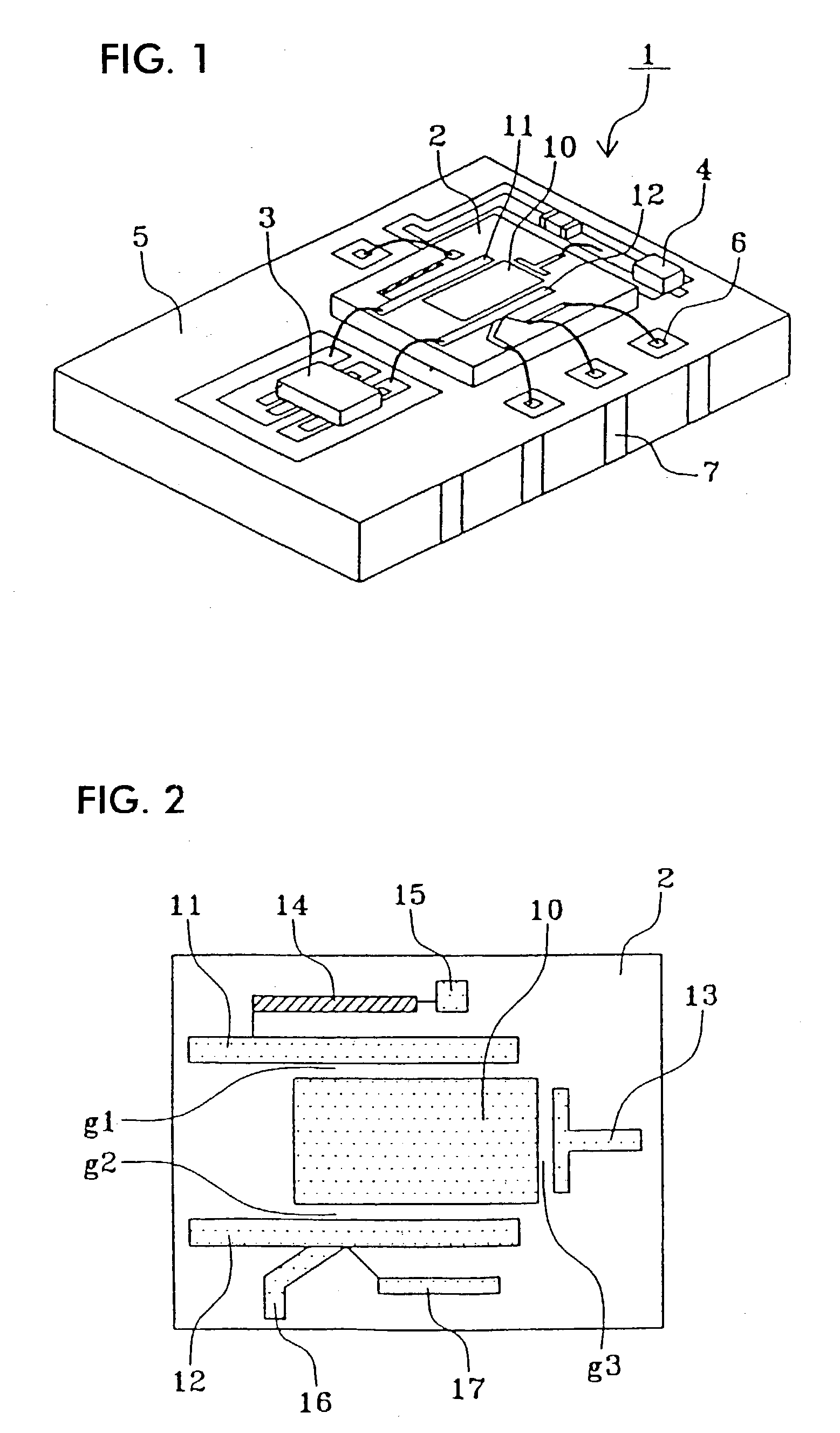
[0036] FIG. 1 is a perspective view of an oscillator according to an embodiment of the present invention. The oscillator 1 shown in FIG. 1 is structured such that a dielectric substrate 2, a transistor 3 which is a resin-molded active device, and a varactor diode 4 which is a resin-molded frequency-variable device are mounted on one main surface of a package substrate 5.

[0037] The package substrate 5 is formed of an alumina substrate having a relatively small dielectric constant (a relative permittivity of about 9 to 10). In addition to lands for mounting the dielectric substrate 2, the transistor 3, and the varactor diode 4, the package substrate 5 has wires for connecting components, and connection lands 6 for wire bonding formed on one main surface thereof. Connection terminals 7 are formed at an end face thereof. The connection terminals 7 are connected to a ground electrode, to lands for mounting components, to wires, and to connection lands all formed on the package substrate ...


PUM


Abstract

PROBLEM TO BE SOLVED: To provide a voltage controlled oscillator providing a strip line resonator in the inside layer of a multilayer substrate and less in the dispersion of oscillation frequency by humidity. SOLUTION: Polytetrafluoroethylene is used as the core material of the multilayer substrate. Since the polytetrafluoroethylene has smaller water absorptivity than glass epoxy, the change of dielectricity to the change of humidity. As a result, also the change of the resonant frequency of the strip line resonator formed in the inside layer of the multilayer substrate is small, as a result, also the change of oscillation frequency becomes small. Then, since the change of the oscillation frequency is small, control voltage sensitivity can be reduced, and thus, C/N characteristics is improved. Then, since also the property of the polytetrafluoroethylene material itself is small in dielectric loss comparing with the glass epoxy and also specific dielectricity is small, the Q of resonant system is improved, and thereby, the C/N characteristics is improved too.

Description

[0001] 1. Field of the Invention[0002] The present invention relates to high-frequency oscillators and electronic apparatus using the oscillators; for example, to an oscillator used as a local oscillator in a communication apparatus, and to other electronic apparatus using the oscillator.[0003] 2. Description of the Related Art[0004] Conventional high-frequency oscillators have structures as disclosed, for example, in Unexamined Japanese Patent Application Publication No. Sho-63-9203 and Unexamined Japanese Patent Application Publication No. Hei-10-173439.[0005] In Unexamined Japanese Patent Application Publication No. Sho-63-9203, an oscillator mainly including a dielectric substrate, a cylindrical dielectric resonator made from a large-dielectric-constant dielectric, a semiconductor device, and a metallic case is disclosed in an outlined manner. The dielectric resonator is mounted on the dielectric substrate through a support dielectric, is covered by the metallic case, resonates,...

Claims


Application Information

Patent Timeline
IPC IPC(8): H03B5/02H01L25/00H03B5/04H03B5/18H05K1/02H05K1/14H05K1/16H05K3/34H05K3/36
CPCH03B5/18H05K1/0237H01L2224/48227H05K1/141H05K1/162H05K3/3442H05K3/368H05K2201/045H05K2201/10068H05K2201/10166H05K2201/10174H05K2203/049H01L2224/48091H01L2924/00014
Inventor IEKI, TSUTOMUIDA, YUTAKA
Owner MURATA MFG CO LTD
Why Eureka
Try Eureka