Electrophoresis in microfabricated devices using photopolymerized polyacrylamide gels and electrode-defined sample injection

Inactive Publication Date: 2003-06-26
THE RGT OF THE UNIV OF MICHIGAN
View PDF4 Cites 22 Cited by
  • Summary
  • Abstract
  • Description
  • Claims
  • Application Information

AI Technical Summary

Benefits of technology

0008] In one embodiment, the present invention relates to a novel, small-scale, electrophoretic separation system based on photodefined p

Problems solved by technology

Genotyping projects on the order of millions of assays, however, are beyond the capabilities of today's laboratories because of the current inefficiencies in (i) liquid handling of reagent and DNA template solutions, (ii) measurement of solution volumes, (iii) mixing of reagent and template, (iv) controlled th

Method used


Image

  • Electrophoresis in microfabricated devices using photopolymerized polyacrylamide gels and electrode-defined sample injection
  • Electrophoresis in microfabricated devices using photopolymerized polyacrylamide gels and electrode-defined sample injection
  • Electrophoresis in microfabricated devices using photopolymerized polyacrylamide gels and electrode-defined sample injection

Examples


Example

EXAMPLE 1

Electrophoresis Procedure

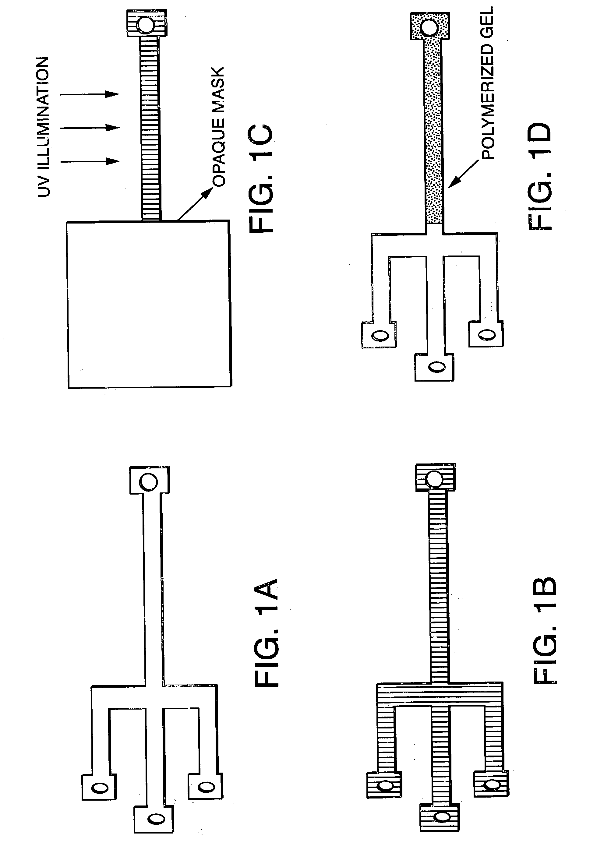
[0090] Prior to electrophoresis runs, the microchannels (prepared as described above) were rinsed with acetone, isopropanol (IPA) and distilled / deionized water to remove particulate and organic matter. Following this clean, the channels were treated with RainX AntiFog solution (Blue Coral, Cleveland, Ohio) to promote uniform wetting on all channel surfaces by the gel reagents. Photopolymerizable polyacrylamide gels were prepared by using the commercial ReproGel.TM. (Amersham Pharmacia, Kalamazoo, Mich.) system (see, U.S. Pat. No. 5,873,991 to Gothe, incorporated herein by reference). The gel solution was prepared by mixing 10 .mu.l of solution A (acrylamide stock solution) with 20 .mu.l of solution B and was loaded into the entire channel network by placing a drop of premixed solution at one end of the separation channel. The device was masked in all sections except where polymerization was desired and exposed to a UVA illumination from a 40 watt me...

Example

EXAMPLE 2

Photopolymerized Polyacrylamide Gels

[0092] Having selected the commercially available UV initiated ReproGel.TM. formulation, the gel casting process was greatly simplified. Two variations of the polymerization mixture were studied: ReproGel.TM. High Resolution, containing 8% (w / v) acrylamide / bisacrylamide monomers and 1.times. TBE buffer, and ReproGel.TM. Long Read, containing 7% (w / v) acrylamide / bisacrylamide monomers and 1.5.times. TBE buffer. The characteristically small dimensions of microfabricated separation channels demand that care be taken to preserve the integrity of the gel during the casting process by avoiding the introduction of impurities and eliminating bubble formation during the polymerization reaction. However, we found that reproducible high-resolution separations were achievable using the as-received reagents, without the need for additional purification and / or degassing.

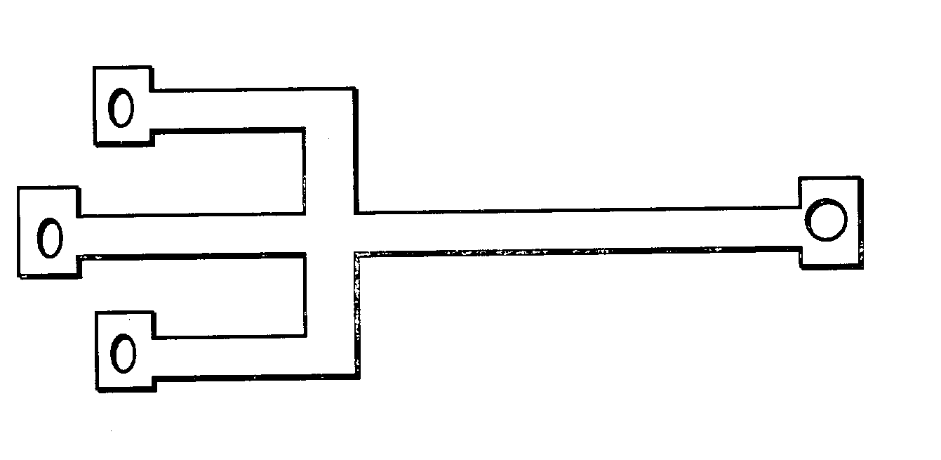
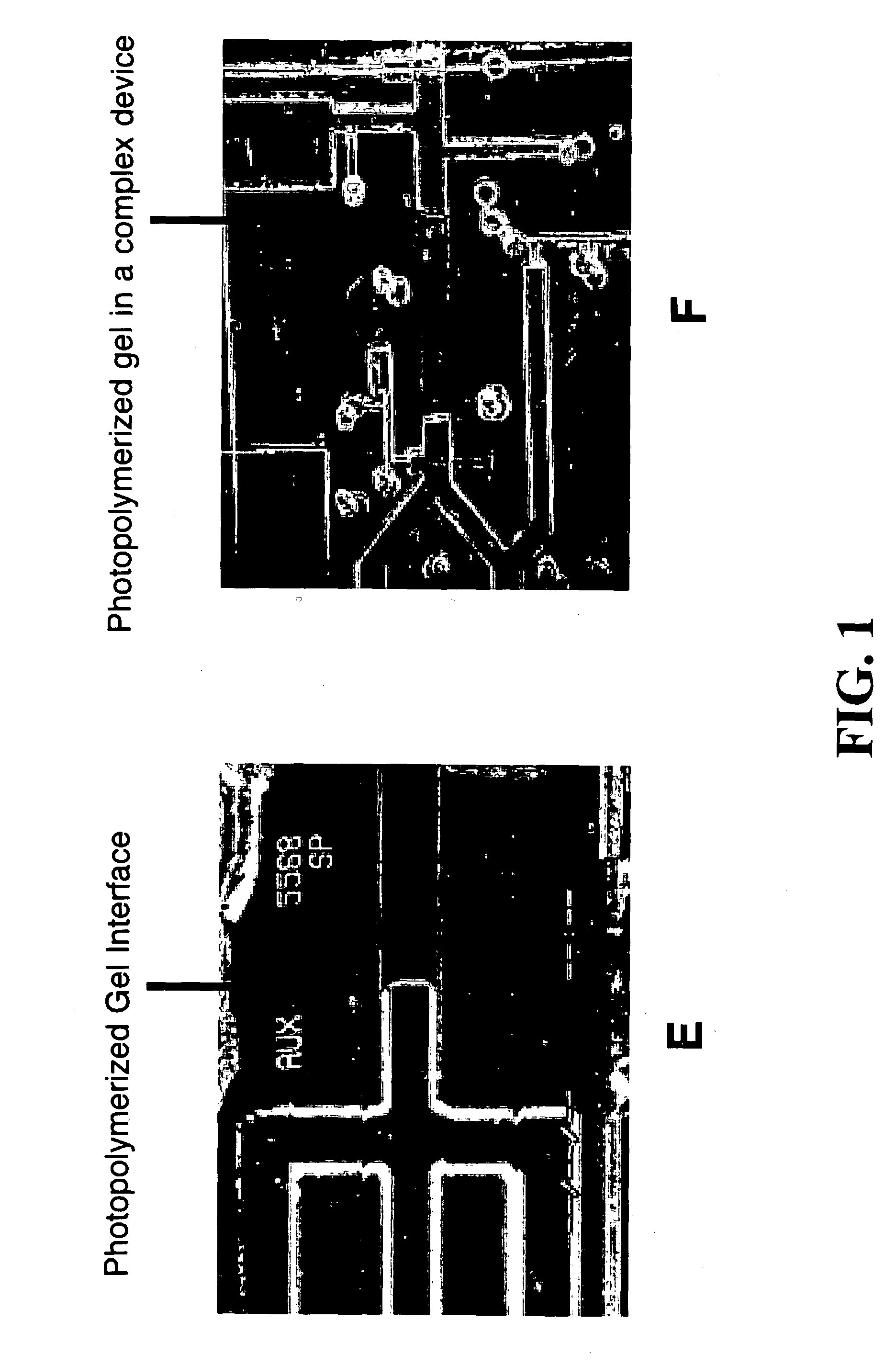
[0093] Flat and uniform gel interfaces in the sample loading region could be achiev...

Example

EXAMPLE 3

Optimization Of Photopolymerization Time

[0095] Optimization of the polymerization protocol focused on adjusting UV intensity and polymerization time, both of which strongly affect the rate of initiation, with the aim of maximizing separation performance with minimal run-to-run variability. The Reproset.TM. UV illumination source (Amersham Pharmacia, Kalamazoo, Mich.), designed specifically for use with the ReproGel.TM. reagents, provided more consistent results than a lower-intensity UV lamp (UVP, San Gabriel, Calif.) and was used as provided in the manufacturers materials. Separation performance was evaluated by observing the migration of a fluorescently labeled 20 base pair molecular ladder (FIGS. 2a-d; samples were directly compacted at the gel interface by application of an electric field (E=10 V / cm) for 20 s. Separation was conducted at E=20 V / cm. Migration direction is left to right. Data shown corresponds to gel polymerization times of (a) 2, (b) 6, (c) 7 and (d) 8 m...


PUM

PropertyMeasurementUnit
Temperatureaaaaaaaaaa
Concentrationaaaaaaaaaa
Sizeaaaaaaaaaa

Abstract

The present invention relates to a novel, small-scale, electrophoretic separation system based on photodefined polymers and electrode-defined sample injection. Diffusion and displacement coefficients may be modified by varying the gel concentration, the intensity of the incident UV radiation and the temperature at which the gel is run. The device is an major advance over current technology since it provides for a significant reduction in size of the micro-electrophoresis apparatus and a significant cost savings.

Description

[0002] The present invention relates to a novel, small-scale, electrophoretic separation system based on photodefined polymers (e.g., polyacrylamide gels) and electrode-defined sample injection giving superior resolution at a reduced cost and in less time.BACKGROUND OF INVENTION[0003] Despite the progress made towards the development of microfabricated DNA analysis systems, there are significant hurdles to the realization of small, portable DNA analysis systems. Although the cross sectional dimensions of typical microfabricated electrophoresis channels are on the order of those employed in conventional capillary systems, scale-down efforts have proven to be less than straightforward. Most of the miniaturized separation systems developed so far have adopted non-crosslinked polymer solutions as the medium of choice for DNA separations. The use of non-cross-linked sieving media necessitates the use of high electric fields to overcome the diffusion / dispersion of DNA fragments in these m...

Claims


Application Information

Patent Timeline
IPC IPC(8): G01N27/447
CPCG01N27/44704G01N27/44791G01N27/44743
Inventor BURNS, MARK A.BRAHMASANDRA, SUNDARESH N.UGAZ, VICTOR M.
Owner THE RGT OF THE UNIV OF MICHIGAN
Why Eureka
Try Eureka