The problem inherent in many conventional fiber optic gyroscopes, however, is that they can be sensitive to excess
noise disturbances at low rotation rates.
For example, the well known Raleigh scattering (i.e., scattering of light due to inhomogeneities in
material density smaller than a
wavelength in size), polarization noise (i.e., polarization fluctuations observed via
voltage fluctuations), and zero rotation drift due to the
Kerr effect (i.e., the development of
birefringence when an isotropic transparent substance is placed in an electrical field) are typical problems which often reduce the accuracy of the
optical gyroscope output by introducing errors in rotation rate sensing.
The downside to using these sources, however, is that due to their finite bandwidth, these
broadband sources introduce an additional excess noise term into the gyro output.
This, in turn, causes a reduction in performance and satisfaction of the fiber optic gyroscope systems.
Unfortunately, where SLDs are implemented in fiber optic gyroscopes, the fiber optic gyroscope generally suffers from a high
wavelength sensitivity to temperature, inefficient
coupling to single-mode fibers, and a lack of
immunity to optical feedback.
Additionally, in a practical
system, unwanted spurious reflections from the source /
system interface can greatly reduce the power which can be coupled to the system fiber.
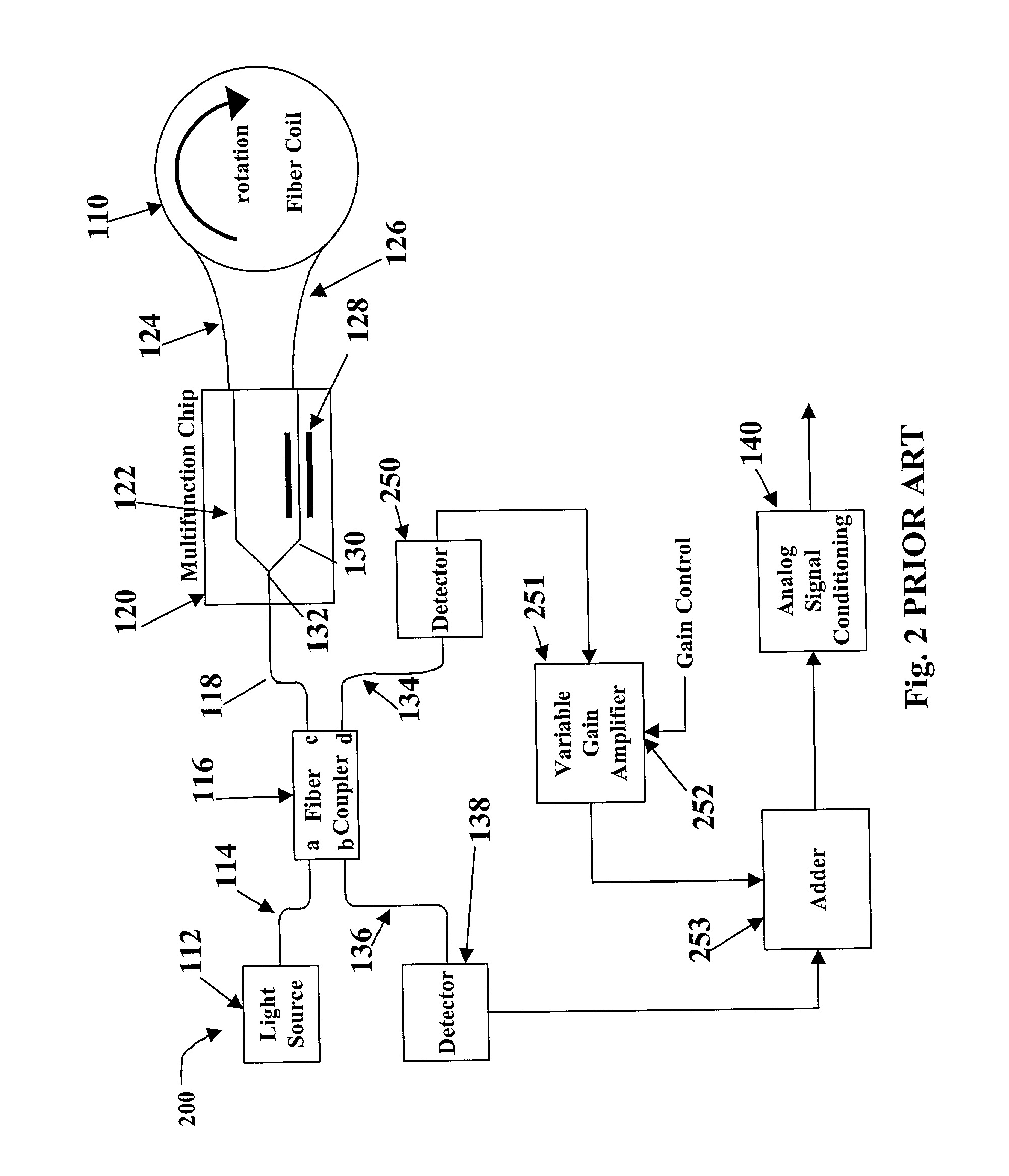
However, imperfections in real optical components such as polarization
crosstalk will limit how much the excess noise is actually reduced.
Moreover, it is important to note that these systems' error in amplitude adjustment will increase as the
system parameters change over time with the aging of the gyro.
The change in
system parameters becomes even more pronounced in systems employing high performance fiber optic gyroscopes, such as space applications which are exposed to
radiation or
submarine navigation applications which encounter an aging mechanism in the coil fiber that causes increased optical loss over time.
As should be understood, the
variable gain amplifier and circuits used to perform the ratiometeric measurements adds undesirable complexity to the design and operation of the gyroscope.
It should be noted, however, that the disadvantages inherent in the "subtraction" technique may typically be overcome by implementing an excess noise
servo.
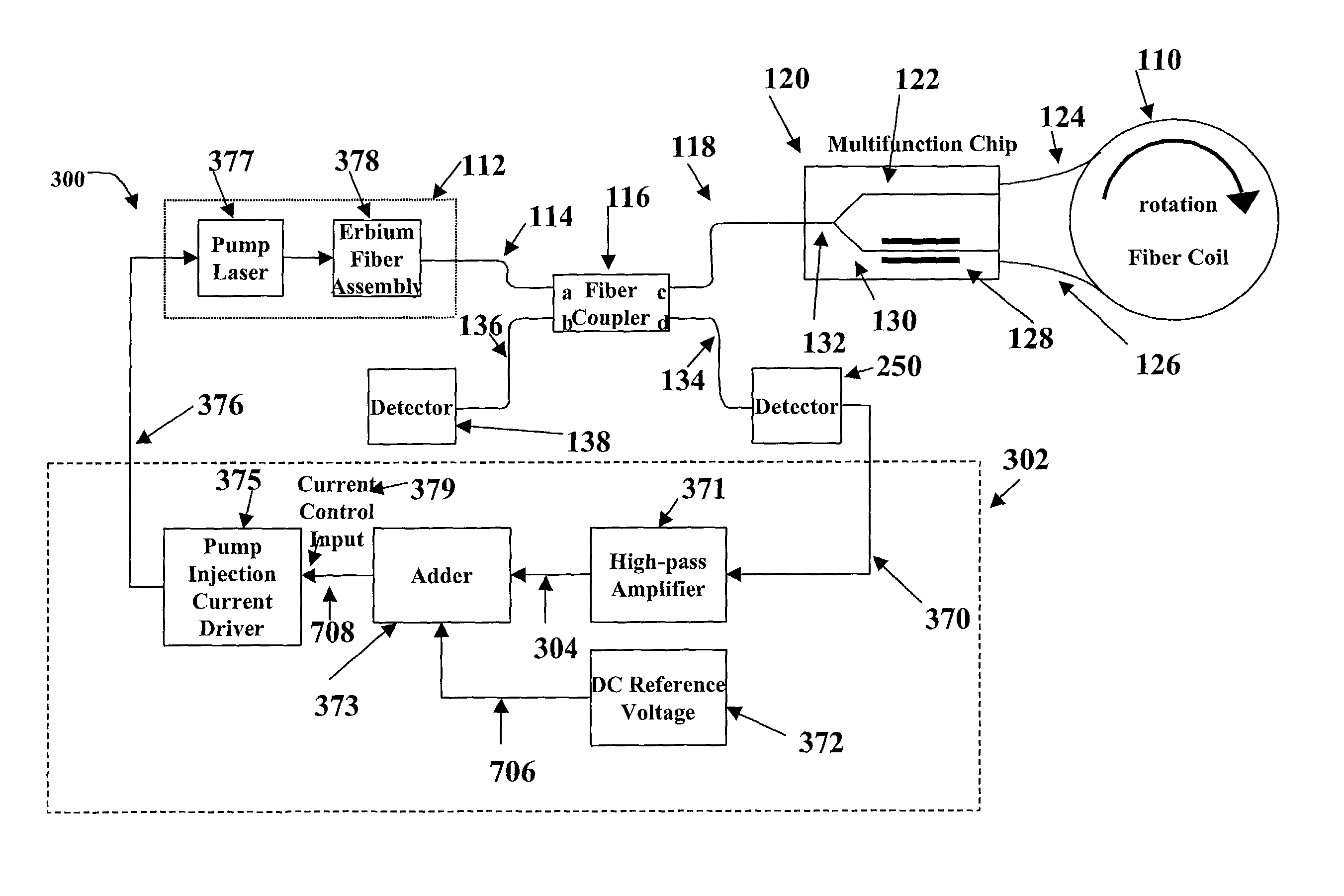
However, where a high performance fiber optic gyroscope used erbium fiber, it was believed that using the subtraction technique with
servo control was impracticable.
For high performance erbium fiber optic gyroscopes, however, it was believed that reducing the excess noise of the gyroscopic system at the
demodulation fundamental, 3 rd and 5 th
harmonics was impracticable because the upper state lifetime of the erbium fiber (e.g., erbium atoms) would limit how fast the output light could be controlled.
That is, previously, fiber optic gyroscope designers thought that after about 100
hertz, the
frequency response of the erbium fiber would be ineffectual for controlling the excess noise output of the gyroscope via the pump current.
Moreover, it was believed that the light output of the erbium fiber
light source couldn't be controlled fast enough to manage intensity variations in the 20 kHz to 50 kHz range.
Furthermore, the designers believed that the bandwidth within which an excess noise
servo could operate in a system using erbium doped
optical fiber would be limited to less than 100 Hz.
Recent experimentation on the frequency response of erbium fiber, however, has yielded different and unexpected results.
If the rolloff was too high, then the control loop would not be useable.
Until now, the use of the properties of the erbium fiber to enhance the
gain in the fiber
optic system has gone untried because of the erroneous belief that the relatively long upper-state life-time of the erbium atoms would limit any control of
light intensity to well below 1 kHz.
Presently known control methods for controlling excess noise gyroscopes using erbium remain inadequate, particularly in their ability to limit excess noise and provide pump current control at low frequencies.

