Pulsed electrolytic cell

a technology of electrolytic cells and electrolytic coatings, applied in the direction of electrolytic coatings, surface reaction electrolytic coatings, coatings, etc., can solve the problems of inability to predict whether such generators will ever be used, decompose into constituent elements, and achieve the effect of increasing resistivity

Inactive Publication Date: 2003-11-20
ENERGETICS TECH
View PDF13 Cites 3 Cited by
  • Summary
  • Abstract
  • Description
  • Claims
  • Application Information

AI Technical Summary

Benefits of technology

[0021] It should be noted that the dense ion packing may substantially increase the resistivity--i.e., the measure of a material's ability to oppose the flow of an electric current--of the metallic electrode by introducing hydrogen, or other, ions to the structure of the metal. This resistivity preferably can be measured in real-time by passing a current through the metallic electrode and measuring the change in current over time. The measured current over time is an indication of the change in resistivity, and, hence, the level of ion packing of the metallic electrode over time. Thus, a real time indicator of the ion packing may then be realized by continually passing a current through the metallic electrode and measuring the current.

Problems solved by technology

Yet despite the multi-billion dollar investments made in developing thermonuclear fusion reactors to produce energy, no such generator is at present a practical reality, and whether it ever will be, cannot be forecast.
When a d-c voltage is impressed across these electrodes, the resultant current flow in the heavy water causes it to decompose into its constituent elements.
In any case, present day electrochemical cells do not generate enough excess heat to be commercially viable power sources.

Method used


Image

  • Pulsed electrolytic cell
  • Pulsed electrolytic cell
  • Pulsed electrolytic cell

Examples


Embodiment Construction

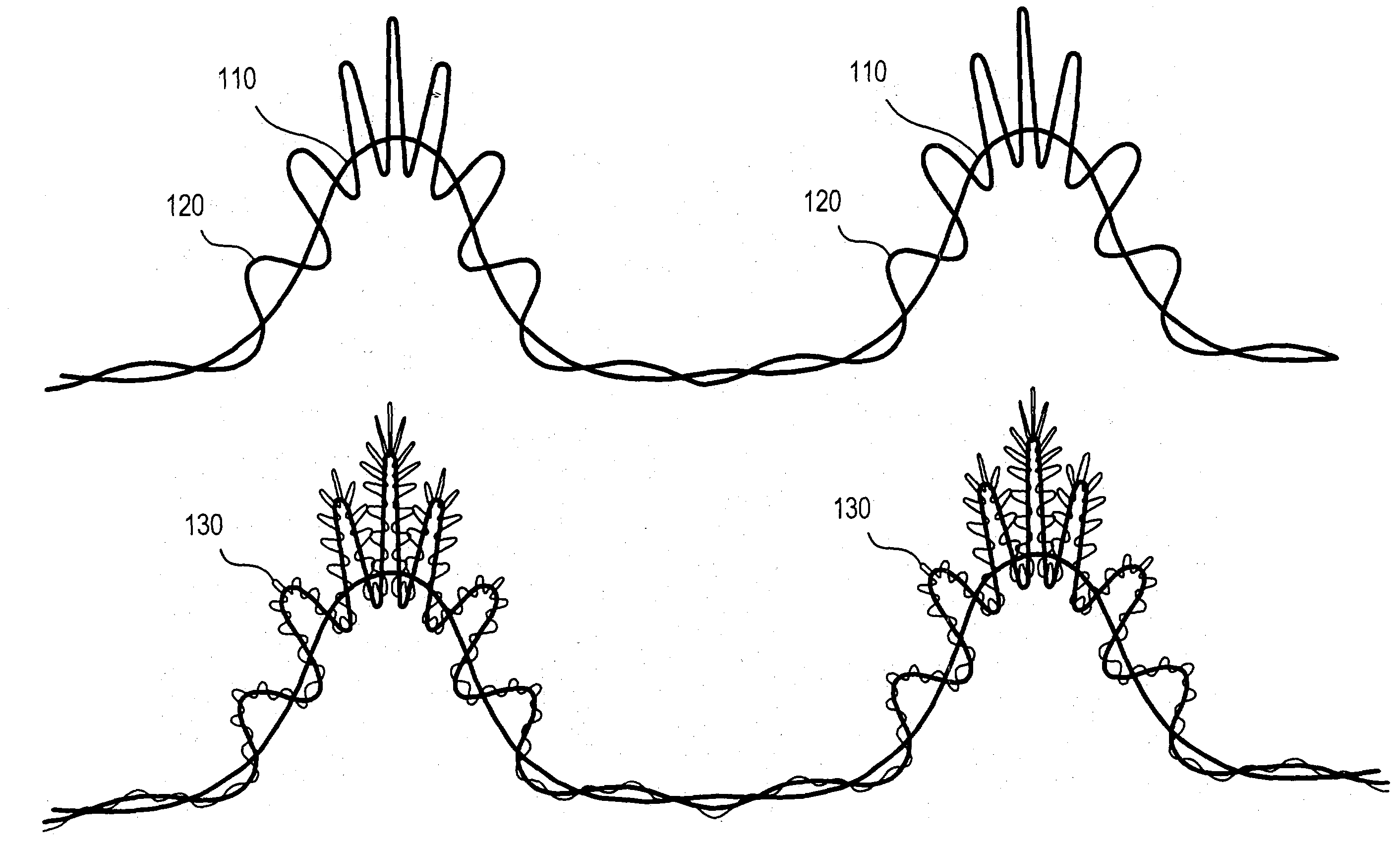
[0027] Superlooping:

[0028] The present invention represents a significant advance beyond the discovery at the Los Alamos National Laboratory that a greater production of excess heat is obtained in an electrochemical cell by pulsing the current flowing through the cell. In the present invention, applied to the electrodes of the cell are voltage pulses to produce a pulsed current flow in the cell. However, these pulses are not of constant amplitude and duration but are in a pattern in which the amplitude and duration of the pulses and the intervals therebetween are modulated to give rise to a dense packing, for example, of deuterium ions in the palladium electrode that promotes a fusion reaction.

[0029] This pulse pattern is in accordance with superlooping activity as set forth in the theory advanced in the Irving I. Dardik article "The Great Law of the Universe" that appeared in the March / April 1994 issue of the "Cycles" Journal. This article is incorporated herein by reference.

[0030]...


PUM

PropertyMeasurementUnit
frequencyaaaaaaaaaa
frequenciesaaaaaaaaaa
energyaaaaaaaaaa

Abstract

A low energy nuclear reaction power generator provided with an electrolytic cell containing an electrically-conductive heavy or light water electrolyte in which is immersed an electrode pair whose anode is formed of platinum and whose cathode is formed of palladium. Applied across these electrodes is a train of voltage pulse packets, each comprised of a cluster of pulses. The amplitude and duration of each pulse in the packet, the duration of the intervals between pulses, and the duration of the intervals between successive packets in the train are in a predetermined pattern in accordance with superlooping waves in which each wave is modulated by waves of different frequency. Each packet of voltage pulses gives rise to a surge of current in the electrolyte which flows between the electrodes and causes the heavy or light water to decompose, oxygen being released at the platinum electrode while deuterium ions migrate toward the palladium electrode. The successive surges of ions produced by the train of pulse packets bombard the palladium electrode, to bring about dense ion packing which results in fusion and heat.

Description

[0001] This application is a continuation of copending, commonly-assigned U.S. patent application Ser. No. 10 / 161,158, filed May 30, 2002, which claims the benefit of copending, commonly-assigned U.S. Provisional Patent Application No. 60 / 294,537, filed May 30, 2001. All of these prior applications are hereby incorporated by reference herein in their entireties.[0002] 1. Field of Invention[0003] This invention relates generally to the use of electrolytic cells for the creation of nuclear fusion and more particularly to a low energy nuclear reaction power generator that includes an electrolytic cell across whose anode and cathode electrodes electrical pulses are applied in a predetermined pattern conducive to fusion.[0004] 2. States of Prior Art[0005] The quest for nuclear fusion to provide an inexhaustible, non-polluting source of energy seeks to exploit the phenomena of nuclear physics. It is known that when two nuclei, for example, of deuterium (heavy hydrogen), fuse together, the...

Claims


Application Information

Patent Timeline
Patent Type & Authority Applications(United States)
IPC IPC(8): C25B11/02C25B1/04C25B9/00C25B9/04C25B15/02G21B3/00
CPCG21B3/00Y02E60/366Y02E30/18G21B3/002Y02E30/10Y02E60/36
Inventor DARDIK, IRVING I.
Owner ENERGETICS TECH
Why Eureka
Try Eureka