Two-dimensional ultrasonic array with asymmetric apertures

a two-dimensional ultrasonic array and aperture technology, applied in the field of two-dimensional ultrasonic arrays with asymmetric apertures, can solve the problems of destructive interference outside the target, transmission and reception of unwanted energy, and more difficult to detect subtle differences in the target, so as to avoid the costs and compromises inherent in the

Inactive Publication Date: 2003-11-27
VON RAMM OLAF PH D +1
View PDF17 Cites 34 Cited by
  • Summary
  • Abstract
  • Description
  • Claims
  • Application Information

AI Technical Summary

Benefits of technology

0060] More specifically, the disclosed sparse array uses an inner array of transmit elements and an outer array of receive elements. In the preferred embodiment, the system using this sparse array does not use apodization for weighting. In the preferred embodiment, the system does not use shared transmit / receive elements and thus avoids the costs and compromises inherent in using shared transmit / receive elements.

Problems solved by technology

The arrays of elements are controlled with phase shifts (timing delays) and possibly by weighting so that signals sent to or received from the target constructively interfere while signals outside of the target destructively interfere.
The secondary lobes 154 are caused by imperfect destructive interference outside of the target area and result in the transmission and reception of unwanted energy.
The energy received from side lobes does not represent information about the target region and makes it more difficult to detect subtle differences in the target.
However, there are practical limits on how many array elements can be added.
1) the cost of the additional transmit or receive element,
2) the cost of the circuits to control or process the information from the element,
3) the problem of cross coupling that occurs when too many wires connected to the various transmit and receive elements are running through the cable connecting the head to the main body of the measurement instrument,
4) the undesired weight added to the measurement instrument head; and
5) if transducers are shared for both transmitting and receiving, it will require transmit / receive switching with its added costs and size.
However, whenever the spacing of elements in a phase array transducer exceeds approximately one half of the wavelength of sound used by the element, the periodic spacing of the elements causes additional unwanted side lobes known in the art as grating lobes.
It is difficult to design such aperiodic arrays in a way that minimizes the secondary lobes.
While the vernier approach was an improvement over the random pattern, the result still had ghost images.
D) Disadvantages of the Method Proposed by Lockwood
The first drawback is the previously described complication associated with having to use an apodization scheme to weigh the individual transmit and / or the individual receive elements in order to obtain a suitable radiation pattern.
In addition to the drawbacks from the use of apodization, there are drawbacks from the use of the shared transmit / receive elements that are necessitated by the overlap between the receive and transmit arrays.
The drawbacks from the use of the shared use elements go beyond the need for multiplexing switches and the need for coordinating the high speed switching of the circuits and wire from one function to the other.
One drawback is the need to protect the ultra low voltage receive circuitry from the high voltages used by the transmit circuit.
Another drawback is that the shared transmit / receive element operates on a single frequency range and there may be reasons why it would be advantageous for the transmit and receive elements to operate on different frequency ranges.
When using a shared transmit / receive element intended to transmit a first frequency and receive back a different frequency, one has difficulty optimizing both the transmit and the receive functions as there is only one transducer crystal with a single range of transducer frequencies.
However, it is actually a disadvantage as having fewer elements provides less opportunity for control through time delays for pulsing and measurement windows, weighting, and other processing tools.
Mechanical movement has a number of shortcomings relative to electronic steering, such as limitations from inertia, problems with wear, and the inability to collect data in a pattern that is independent of the mechanical properties of the mechanical equipment.
One limitation of this approach is the use of weighting or apodization because of the cost of the added circuit complexity.
Another, limitation is the large number of elements required for this scheme.

Method used


Image

  • Two-dimensional ultrasonic array with asymmetric apertures
  • Two-dimensional ultrasonic array with asymmetric apertures
  • Two-dimensional ultrasonic array with asymmetric apertures

Examples


first embodiment

[0074] FIG. 4 describes the present invention.

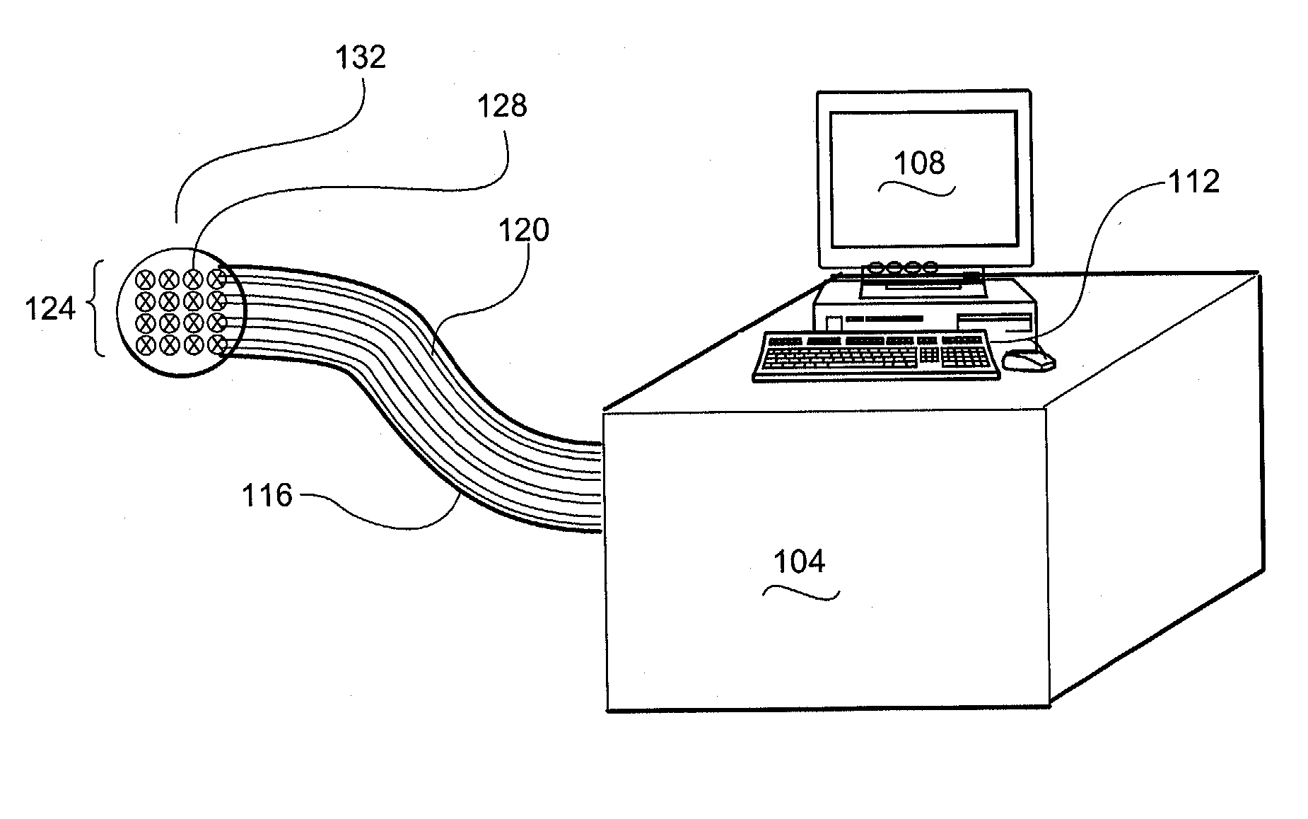
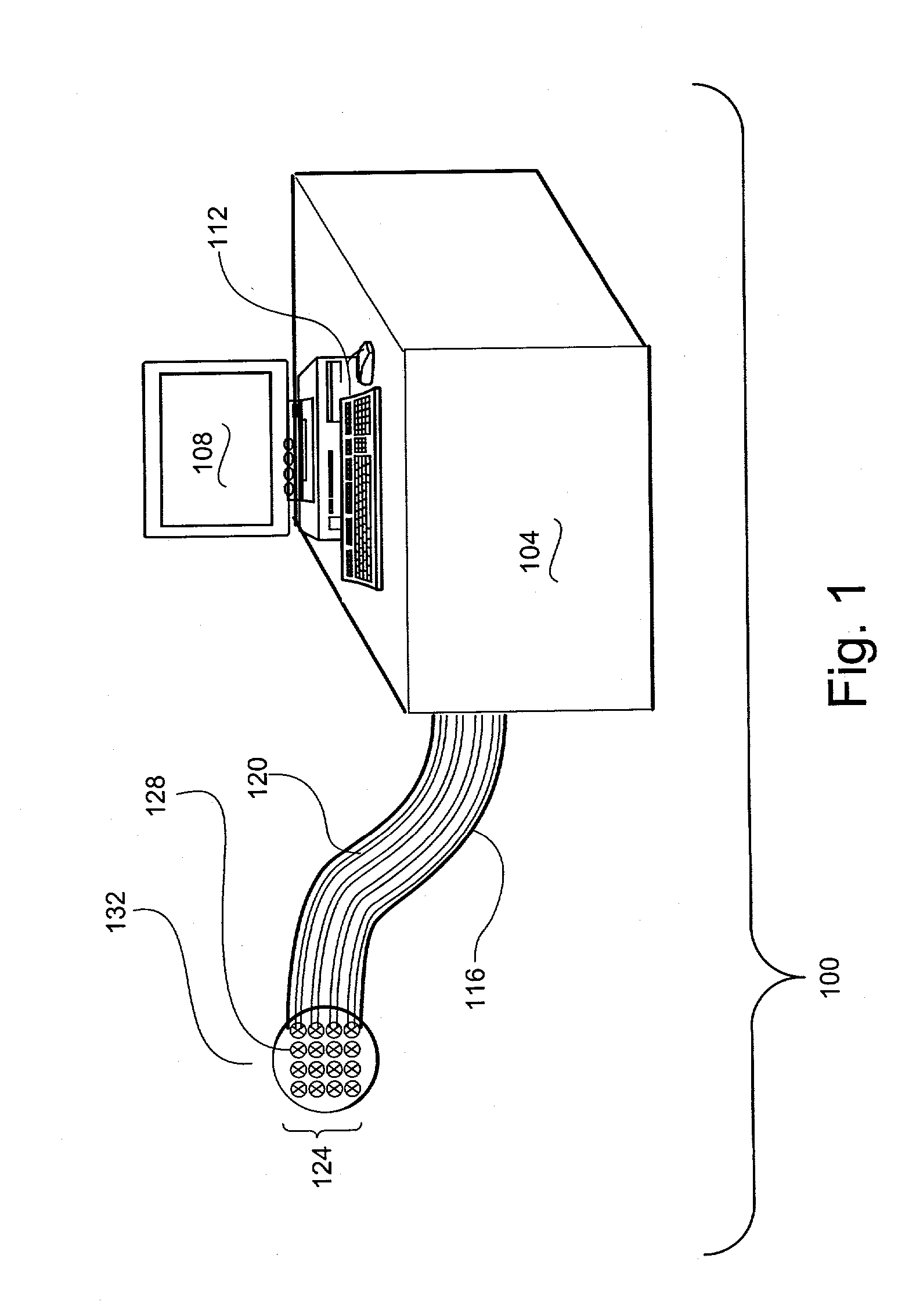
[0075] The sparse array 400 is centered around a center axis 404. (Compare with FIG. 7 that has two centers, one for receive and one for transmit.) The sparse array has an inner transmit array 410 and an outer receive array 420. The inner transmit array is comprised of a series of transmit elements 414. The transmit array is located in the region defined by a circle with midpoint at the center axis 404 and outer perimeter defined by radius R.sub.(TO) 418. In the preferred embodiment the region of the transmit array is fully populated, that is the transmit elements are spaced at no more than approximately 0.5 lambda apart.

[0076] The outer receive array 420 is comprised of a series of receive elements 424 located in an annular area around center axis 404 between the radius R(Ti) and R.sub.(TO). In the preferred embodiment the region of the receive array is fully populated, that is the receive elements are spaced at no more than approximate...


PUM


Abstract

A sparse array that uses a small fraction of a fully populated array but yields a radiation pattern that is suitable for high quality medical imaging. The sparse array consists of two or more separate zones for transmitting and receiving as opposed to the overlapping arrays of the prior art. More specifically, a preferred embodiment sets forth an inner array of transmit elements with a narrow effective aperture and a separate non-overlapping outer array of receive elements with a wide effective aperture. The combination of asymmetric apertures is particularly useful for parallel processing applications. This abstract is provided as a tool for those searching for patents, and not as a limitation on the scope of the claims.

Description

GENERAL[0002] For the convenience of the reader, applicant has added a number of topic headings to make the internal organization of this specification apparent and to facilitate location of certain discussions. These topic headings are merely convenient aids and not limitations on the text found within that particular topic.[0003] In order to promote clarity in the description, common terminology for components is used. The use of a specific term for a component suitable for carrying out some purpose within the disclosed invention should be construed as including all technical equivalents which operate to achieve the same purpose, whether or not the internal operation of the named component and the alternative component use the same principles. The use of such specificity to provide clarity should not be misconstrued as limiting the scope of the disclosure to the named component unless the limitation is made explicit in the description or the claims that follow.[0004] This inventio...

Claims


Application Information

Patent Timeline
Patent Type & Authority Applications(United States)
IPC IPC(8): A61B8/12G01S15/89G10K11/34
CPCA61B8/12G10K11/34G01S15/8925A61B8/4488
Inventor GRENON, STEPHEN MICHAELHILEMAN, RONALD E.
Owner VON RAMM OLAF PH D
Why Eureka
Try Eureka