
Vinylidene fluoride polymer having a fraction of non-transferred chains and its manufacturing process

a technology of vinyl fluoride and non-transferred chains, which is applied in the field of vinyl fluoride polymers having a fraction of non-transferred chains and its manufacturing process, can solve the problems of affecting the strength of fluoropolymers and particularly pvdf, and the toughness of the material is usually very poor, and the impact strength is not always sufficien

Inactive Publication Date: 2003-12-04
ATOFINA
View PDF9 Cites 12 Cited by
  • Summary
  • Abstract
  • Description
  • Claims
  • Application Information

AI Technical Summary

Benefits of technology

[0030] The invention makes it possible to improve the impact strength properties and the fineness of the morphology of PVDF merely by modifying the synthesis conditions, and more specifically by optimizing the way in which the transfer agent is introduced during polymerization and by initially using a water-soluble non-organic initiator. This process change takes place without any change to the apparatus for manufacturing the polymer and can thus be very rapidly transposed to an industrial production line.

Problems solved by technology

VF.sub.2-based fluoropolymers and particularly PVDF have an impact strength which is not always sufficient.
This drawback may have dramatic consequences as it may lead to the fracture of a part, either after a mechanical impact or after an unplanned period of time within a temperature range in which the toughness of the material is usually very poor (T.congruent.-30.degree. C.).
The incorporation of a plasticizing additive or elastomer is effective, but it poses problems of homogenization of the blend and of thermal or chemical stability depending on the nature of these additives.
Among the negative consequences of such a morphology may be distinguished, for example, a high microroughness of objects obtained by melt processing, lack of gloss or a poor surface finish, and a lower transparency of the final material.
In addition, a degradation in the mechanical properties upon prolonged contact with corrosive chemical substances may also result from a surface crystalline morphology which is not fine enough.

Method used


Image

  • Vinylidene fluoride polymer having a fraction of non-transferred chains and its manufacturing process

Examples


example 1

[0076] 18.6 l of deionized water and 50 g of a perfluorinated anionic surfactant of the C.sub.8F.sub.17CO.sub.2NH.sub.4 type were introduced into a 30-litre autoclave.

[0077] The autoclave was closed and mechanically stirred intermittently, then vacuum-degassed, filled with nitrogen at a pressure of up to 10 bar, vacuum-degassed again, filled with VF.sub.2 at a pressure of up to 5 bar and finally vacuum-degassed a last time. Next, the autoclave was heated to 85.degree. C., the mechanical stirring being at 150 rpm, and then filled with VF.sub.2 at an absolute pressure of up to 85 bar.

[0078] A 50 ml dose of a 0.5% by weight aqueous solution of potassium persulphate was added in a single step in order to start the reaction. The pressure was maintained at 85 bar by the continuous introduction of VF.sub.2.

[0079] When 2.25 g of VF.sub.2 had been consumed, 250 ml of ethyl acetate (EA) and 70 ml of the same aqueous potassium persulphate solution were added.

[0080] When 9 kg of VF.sub.2 had be...

example 2

[0083] The procedure was as in Example 1, except for the additional introduction of 200 ml of EA when 9 kg of VF.sub.2 had been consumed.

example 3

VF.sub.2 / HFP Copolymer

[0084] The procedure was as in Example 1, except for the introduction of 105 g of hexafluoropropylene (HFP) after the initial degassing and before the pressurization to 85 bar and the feed with a VF.sub.2 / HFP mixture containing 1% by weight of HFP up to 2.25 kg of mixture consumed. After introducing the EA when the VF.sub.2 / HFP mixture had been added, the reaction was continued with just VF.sub.2.


PUM

PropertyMeasurementUnit
sizeaaaaaaaaaa
sizeaaaaaaaaaa
shear moduliaaaaaaaaaa

Abstract

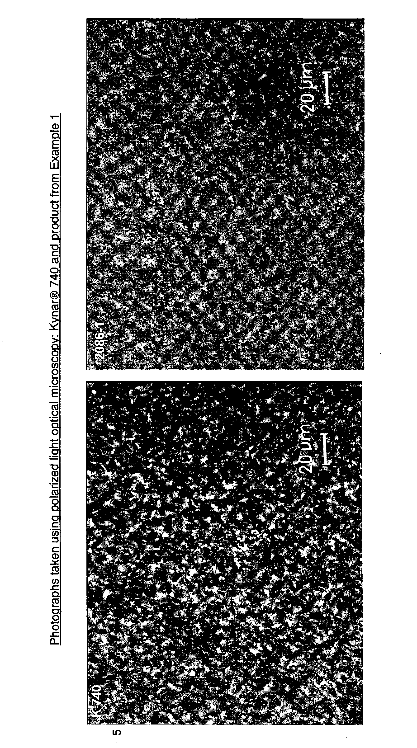
The invention is a PVDF (polyvinylidene fluoride) homopolymer or copolymer, the comonomer being chosen from compounds containing a vinyl group capable of being opened by the action of free radicals in order to be polymerized and which contains, directly attached to this vinyl group, at least one fluorine atom, a fluoroalkyl group or a fluoroalkoxy group such that: it comprises a fraction of non-transferred chains of very high molar mass which are completely insoluble in the usual solvents for PVDF, such as DMF (dimethylformamide), DMSO (dimethyl sulphoxide) and NMP (N-methylpyrrolidone), the polymer fraction associated with these high-mass chains having a dynamic viscosity of greater than 50 kpoise at 230° C. and at a shear rate of 100 s<-1>, the size of the spherulites is between 0.5 and 4 mum. The invention also relates to blends of this PVDF with an ABC triblock copolymer, the three blocks A, B and C being linked together in this order, each block being either a homopolymer or a copolymer obtained from two or more monomers, the A block being linked to the B block and the B block to the C block by means of a covalent bond or of an intermediate molecule linked to one of these blocks via a covalent bond and to the other block via another covalent bond, and such that: the A block is compatible with PVDF, the B block is incompatible with PVDF and is incompatible with the A block, the C block is incompatible with PVDF, the A block and the B block. The invention also relates to the parts made of the above composition. These parts may be sheets, films, tubes, rods, centrifugal pump components and containers. The invention also relates to a process for synthesizing this PVDF, in which: a dispersion of VF2 (vinylidene fluoride) and of one or more optional comonomers in water is made, possibly with the aid of a surfactant, the said dispersion being initially brought into contact with a water-soluble non-organic initiator capable of causing the polymerization of the monomers; then, part of the PVDF having been formed in the presence of the water-soluble non-organic initiator, the following are added: either (i) a chain transfer agent capable of propagating the polymerization, the said polymerization then being initiated by a water-soluble non-organic initiator or by an organic initiator, or (ii) an organic initiator, also capable of accomplishing chain transfer, and optionally a water-soluble non-organic initiator.

Description

[0001] Polymers based on vinylidene fluoride (VF.sub.2), such as PVDF (polyvinylidene fluoride) for example, are known to provide excellent mechanical stability properties, very high chemical inertness and good ageing resistance. These properties are exploited in varied fields of application. Mention may be made, for example, of the manufacture of extruded or injection-moulded parts for the chemical engineering industry or for microelectronics, use in the form of sealing sleeves for the transportation of gases or hydrocarbons, production of films or coatings providing protection in the architectural field and production of protective components for electro-technical uses.PRIOR ART AND TECHNICAL PROBLEM[0002] VF.sub.2-based fluoropolymers and particularly PVDF have an impact strength which is not always sufficient. This drawback may have dramatic consequences as it may lead to the fracture of a part, either after a mechanical impact or after an unplanned period of time within a tempe...

Claims


Application Information

Patent Timeline
Patent Type & Authority Applications(United States)
IPC IPC(8): C08F2/22C08F14/22C08L27/16C08L53/00C08L53/02C08L55/00
CPCC08L27/16C08L53/02C08L55/005C08L2666/24
Inventor PASCAL, THIERRY
Owner ATOFINA
Learn More