Method of forming ceramic beads

a technology of ceramic beads and spherical beads, which is applied in the field of substantially spherical ceramic beads, can solve the problems of difficulty in obtaining ceramic beads having a substantially mono-modal size distribution, the limitation and drawbacks of prior art methods of forming ceramic beads, and the requirement of additional processing

Inactive Publication Date: 2004-01-15
CERCO
View PDF10 Cites 51 Cited by
  • Summary
  • Abstract
  • Description
  • Claims
  • Application Information

AI Technical Summary

Benefits of technology

0028] The aqueous gelling solution preferably comprises an aqueous solution of calcium chloride. It will be appreciated that other soluble salts such as any polyvalent salt with an ionic radius greater than Mg.sup.+2 can be used. The concentration of the calcium chloride can be within the range of from about 5% to about 25% by weight in water, which is preferably distilled. The gelling solution causes the solid ceramic particles in the slurry to dehydrate and form a gel, thus giving the bead a rigid form.

Problems solved by technology

The limitations and drawbacks associated with prior art methods of forming ceramic beads are well known.
One of the most significant drawbacks is the difficulty in obtaining ceramic beads having a substantially mono-modal size distribution in the absence of substantial post-bead formation processing.
This results in requirement for additional processing, such as classification, in order to obtain beads having only the desired size.
It also results in waste.
Another limitation of prior art methods of forming ceramic beads is that the beads themselves tend not to be substantially spherical.
Uniform sphericity is highly desired but difficult to obtain using prior art methods.
Other limitations of prior art methods include, for example, difficulties in controlling the size of the beads formed, the materials that can be used, and the production rate.

Method used


Image

  • Method of forming ceramic beads
  • Method of forming ceramic beads
  • Method of forming ceramic beads

Examples


example ii

[0042] An alginate solution was prepared by mixing 2 g. ammonium alginate powder with 64 g. distilled water in a high shear mixer. The alginate solution was allowed to hydrate for 24 hours. A slurry was prepared by mixing:

[0043] (i) 66 g. of the alginate solution;

[0044] (ii) 275 g. of a ceramic powder consisting of 100% by weight commercial quality ceria stabilized tetragonal zirconia particulates (Ce-TZP) having an average particle size of 0.5 .mu.m;

[0045] (iii) 50 g. distilled water; and

[0046] (iv) 2.5 g. of a dispersant available from Zschimmer und Schwarz GmbH & Co. Chemische Fabriken, Lahnstein, Germany as DOLAPIX PC33.

[0047] The slurry was milled in an Attritor mill for 1 hour using 1650 g. of 3 mm yttria stabilized zirconia media.

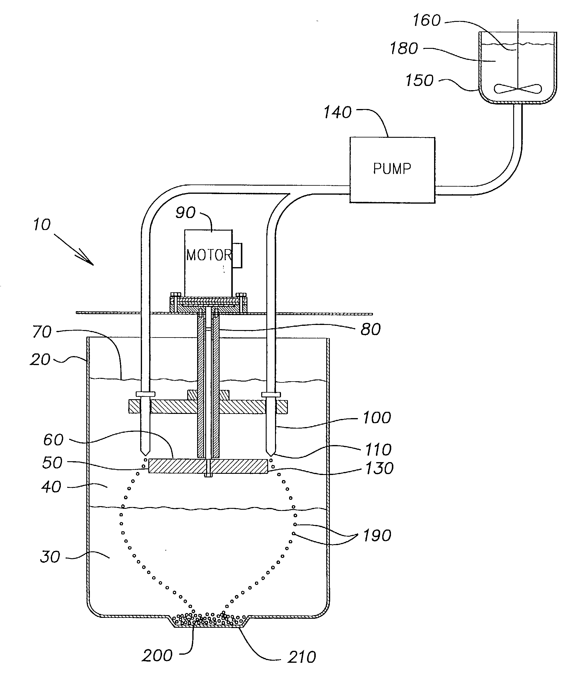
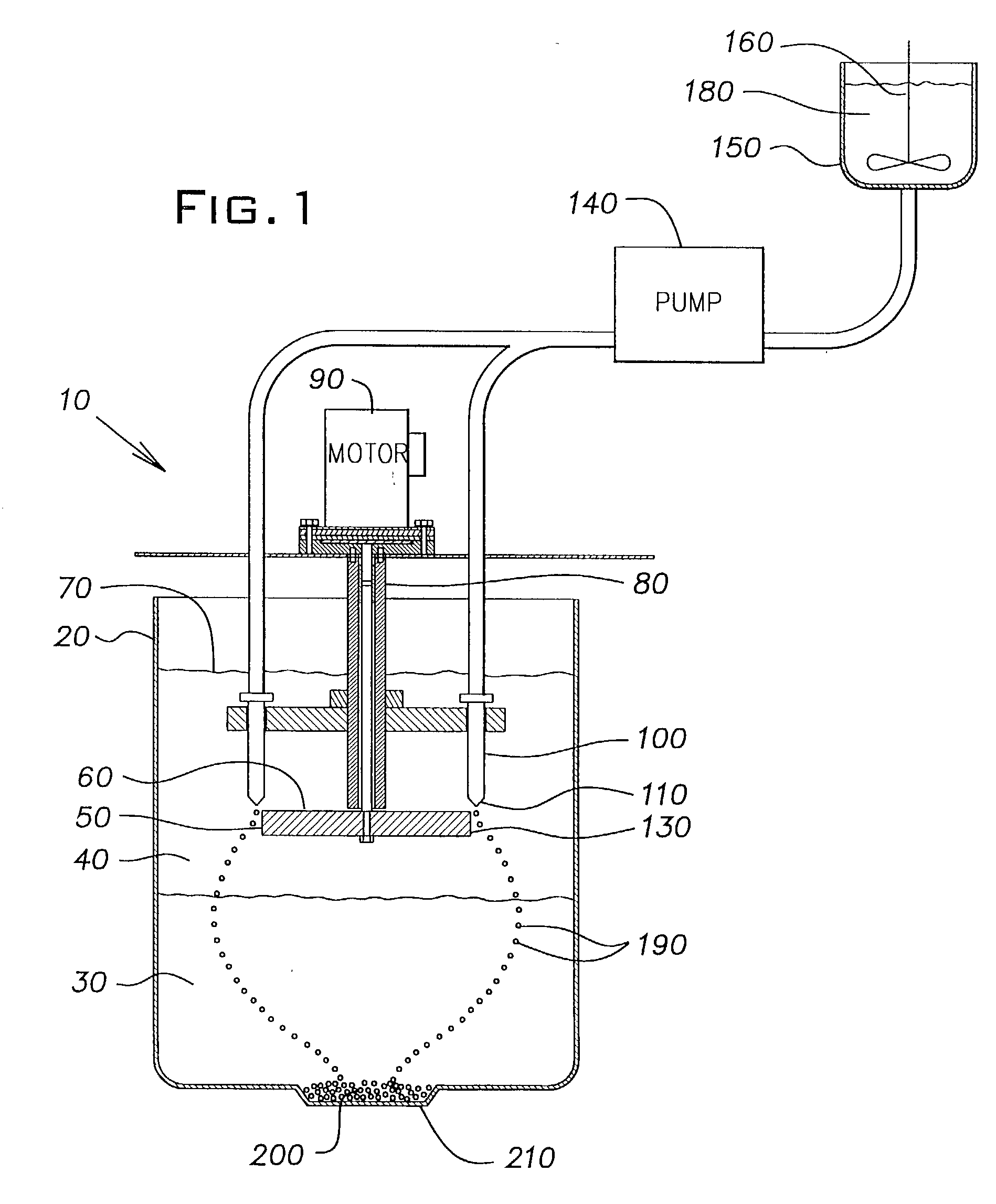
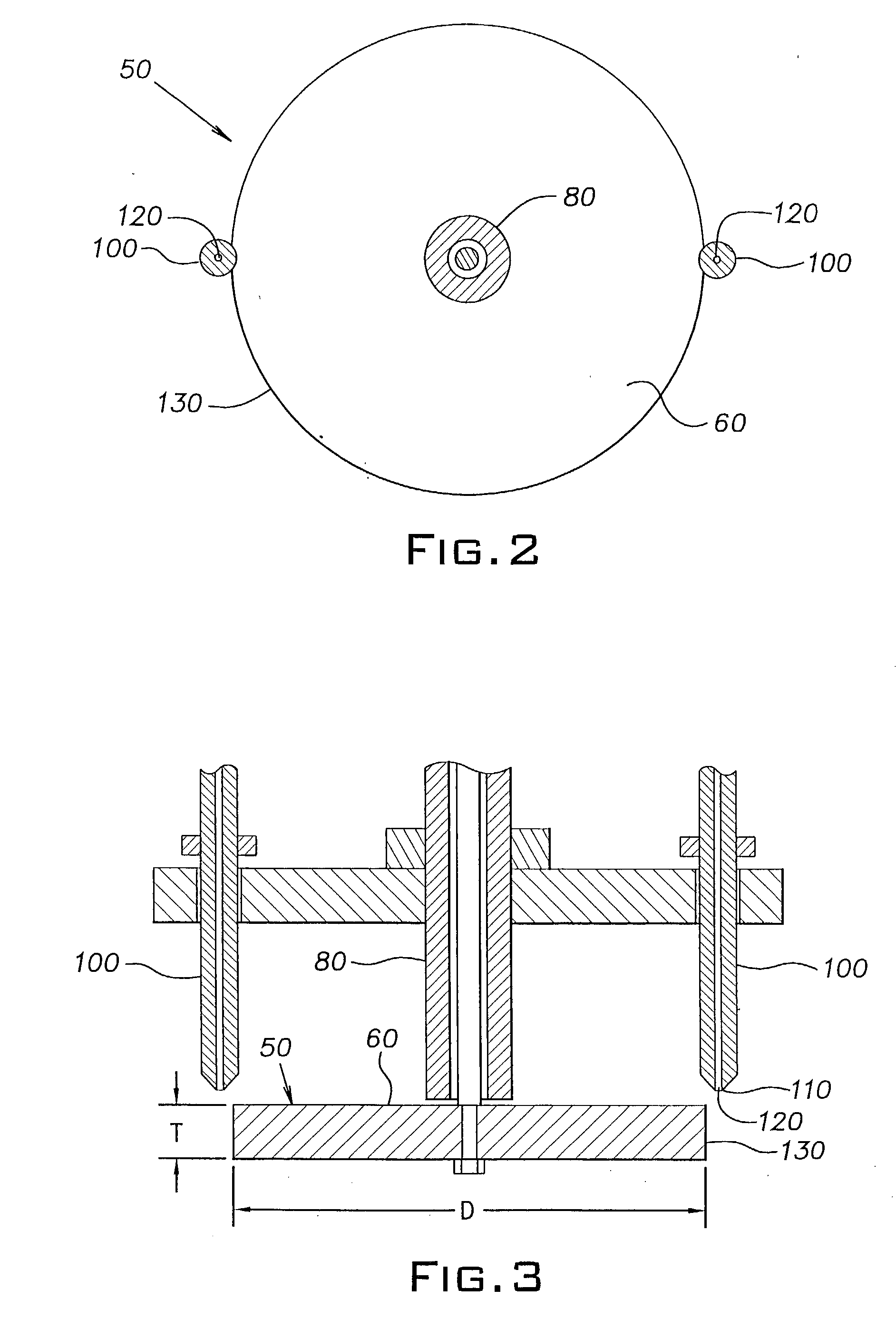
[0048] The slurry was pumped into mineral spirits using the same apparatus and conditions as described in Example 1, except that the disk was rotated at 200 rpm and the flow rate of the slurry through the orifice in the nozzle tip was 8 ml / min. The r...

example iii

[0049] An alginate solution was prepared by mixing 3 g. ammonium alginate powder with 97 g. distilled water in a high shear mixer. The alginate solution was allowed to hydrate for 24 hours. A slurry was prepared by mixing:

[0050] (i) 100 g. of the alginate solution;

[0051] (ii) 300 g. of a ceramic powder consisting of 88% by weight zircon powder (1 .mu.m average), 3% by weight of a glass frit sold by Ferro Corporation under the trade designation 3851, and 9% by weight colloidal silica sold by Nalco as AG1050;

[0052] (iii) 30 g. distilled water; and

[0053] (iv) 3 g. of a dispersant available from R. T. Vanderbilt as DARVAN 821-A.

[0054] The slurry was milled in an Attritor mill for 1 hour using 1650 g. of 3 mm yttria stabilized zirconia media.

[0055] The slurry was pumped into mineral spirits using the same apparatus and conditions as described in Example 1. The rigid beads formed in the calcium chloride solution were washed and dried as described in Example 1, and then fired in a high tem...

example iv

[0056] An alginate solution was prepared by mixing 3 g. ammonium alginate powder with 97 g. distilled water in a high shear mixer. The alginate solution was allowed to hydrate for 24 hours. A slurry was prepared by mixing:

[0057] (i) 100 g. of the alginate solution;

[0058] (ii) 300 g. of a ceramic powder consisting of 88% by weight zircon powder (1 .mu.m average), 6% by weight of a ball clay sold under the trade designation as HUBER J2, 5% by weight colloidal silica sold by Nalco as AG1050, and 2% by weight talc;

[0059] (iii) 30 g. distilled water; and

[0060] (iv) 3 g. of a dispersant available from R. T. Vanderbilt as DARVAN 821-A.

[0061] The slurry was milled in an Attritor mill for 1 hour using 1650 g. of 3 mm yttria stabilized zirconia media.

[0062] The slurry was pumped into mineral spirits using the same apparatus and conditions as described in Example 1. The rigid beads formed in the calcium chloride solution were washed and dried as described in Example 1, and then fired in a high...


PUM

PropertyMeasurementUnit
sphericityaaaaaaaaaa
diameteraaaaaaaaaa
diameteraaaaaaaaaa

Abstract

A method of forming substantially spherical ceramic beads that includes conveying an aqueous ceramic slurry to a nozzle tip that is immersed in an inert water-immiscible fluid layer. The nozzle tip is spaced a predetermined distance away from a rotating disk that is also immersed in the immiscible fluid layer. The rotating disk creates a shear force that at the nozzle tip that dislodges droplets of the aqueous ceramic slurry from the nozzle tip into the immiscible fluid layer. Once dislodged, the droplets assume a substantially spherical shape and a substantially mono-modal size distribution. The droplets are permitted to pass from the immiscible fluid layer into an aqueous gelling solution wherein the droplets are converted into rigid beads. In a preferred embodiment of the invention, the rigid beads are recovered from the gelling solution, washed, and then sintered to obtain a density of greater than about 98% of theoretical density and a sphericity of greater than about 0.95. The method can be used to fabricate substantially spherical zirconia-containing beads having a diameter within the range of from about 0.1 mm to about 2.0 mm that are useful, for example, as grinding media.

Description

[0001] The present invention provides a method of forming substantially spherical ceramic beads.[0002] Ceramic beads are useful in a number of applications including, for example, as grinding media, catalyst supports, adsorbent materials, and pen balls. There are a number of known methods of forming ceramic beads, with the "spray dry" and "oil-drop" methods being most widely used. In both of these methods, an aqueous ceramic bead forming liquid is dispensed into droplets which are then hardened. In the "spray dry" method, all or part of the hardening takes place in a stream of air. In the "oil-drop" method, at least a portion of the hardening occurs while the droplets are dispersed in a water-immiscible liquid, such as mineral oil. In some cases, the ceramic beads are formed using a combination of the various aspects of the "spray dry" and "oil drop" methods. Representative examples of prior art methods of forming ceramic beads are disclosed in: Elliott, U.S. Pat. No. 3,457,335; Sch...

Claims


Application Information

Patent Timeline
Patent Type & Authority Applications(United States)
IPC IPC(8): B01J2/06B28B1/00C04B35/16C04B35/44C04B35/462C04B35/48
CPCB01J2/06C04B2235/94C04B35/01C04B35/16C04B35/44C04B35/462C04B35/48C04B35/481C04B35/486C04B35/62625C04B35/62635C04B2235/3206C04B2235/3217C04B2235/3229C04B2235/3248C04B2235/3409C04B2235/3418C04B2235/3445C04B2235/3481C04B2235/349C04B2235/36C04B2235/528C04B2235/5296C04B2235/5427C04B2235/5445C04B2235/765C04B2235/77C04B2235/80B28B1/004
Inventor VLACH, THOMAS J.YAROSHENKO, VIKTORPUJAR, VIJAY V.
Owner CERCO
Why Eureka
Try Eureka