Polishing pad and multi-layer polishing pad

Inactive Publication Date: 2004-01-22
JSR CORPORATIOON
View PDF13 Cites 66 Cited by
  • Summary
  • Abstract
  • Description
  • Claims
  • Application Information

AI Technical Summary

Problems solved by technology

Even when the technique is used, however, in some cases, scratch cannot be sufficiently inhibited from being formed on a polished surface of a material to be polished.
Even when these techniques are used, however, in some cases, pores cannot be suppressed from being clogged by abrasive and polishing wastages during polishing, or pores cannot be suppressed from being clogged after dressing, and thereby, the removal rate cannot be sufficiently improved.
Still furthermore, in some cases, the slurry cannot be sufficiently uniformly distributed on the polishing pad; accordingly, the removal rate cannot be sufficiently improved and a sufficiently uniform polished surface cannot be obtained.
When there is large unevenness, a particularly large convex portion (made of, for instance, cutting residue generated when the groove is formed) drops off during polishing, resulting in causing scratches.
Furthermore, foreign matters formed from the dropped off convex portion by compressing or the like owing to a pressure and friction heat during polishing, foreign matters formed from the dropped off convex portion and polishing wastage, solid component in the slurry and the like by interacting to form foreign matters may occur the scratches in some cases.
In addition, even during dressing, in some cases, the convex portion may drops off, resulting in the similar inconvenience.
When the depth of the groove is less than 0.1 mm, it is not preferable because the lifetime of the polishing pad becomes excessively short.
It also tends to be difficult to form the concave portion or the like whose smallest length is less than 0.05 mm.
Of these, in the former, the water-soluble particles are brought into contact with a water-based medium component of the slurry (

Method used


Image

  • Polishing pad and multi-layer polishing pad
  • Polishing pad and multi-layer polishing pad
  • Polishing pad and multi-layer polishing pad

Examples


example 1-1

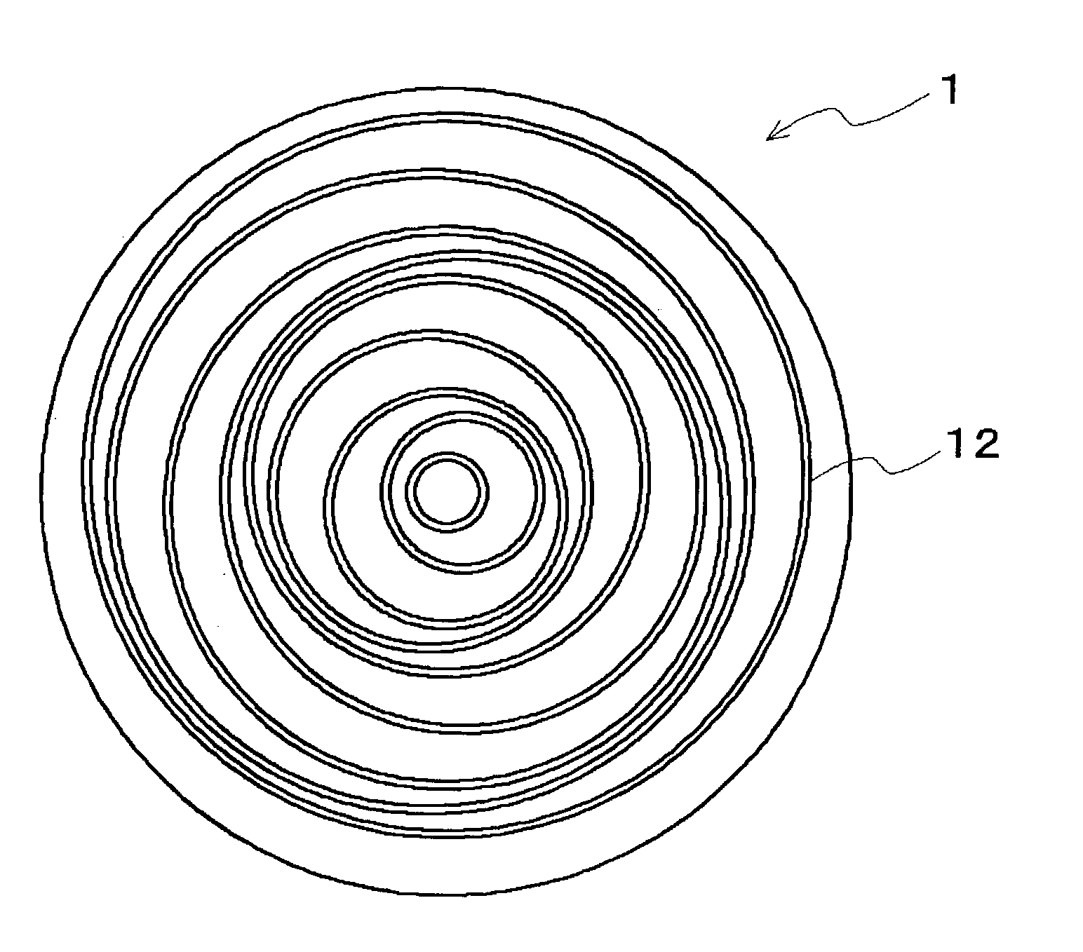
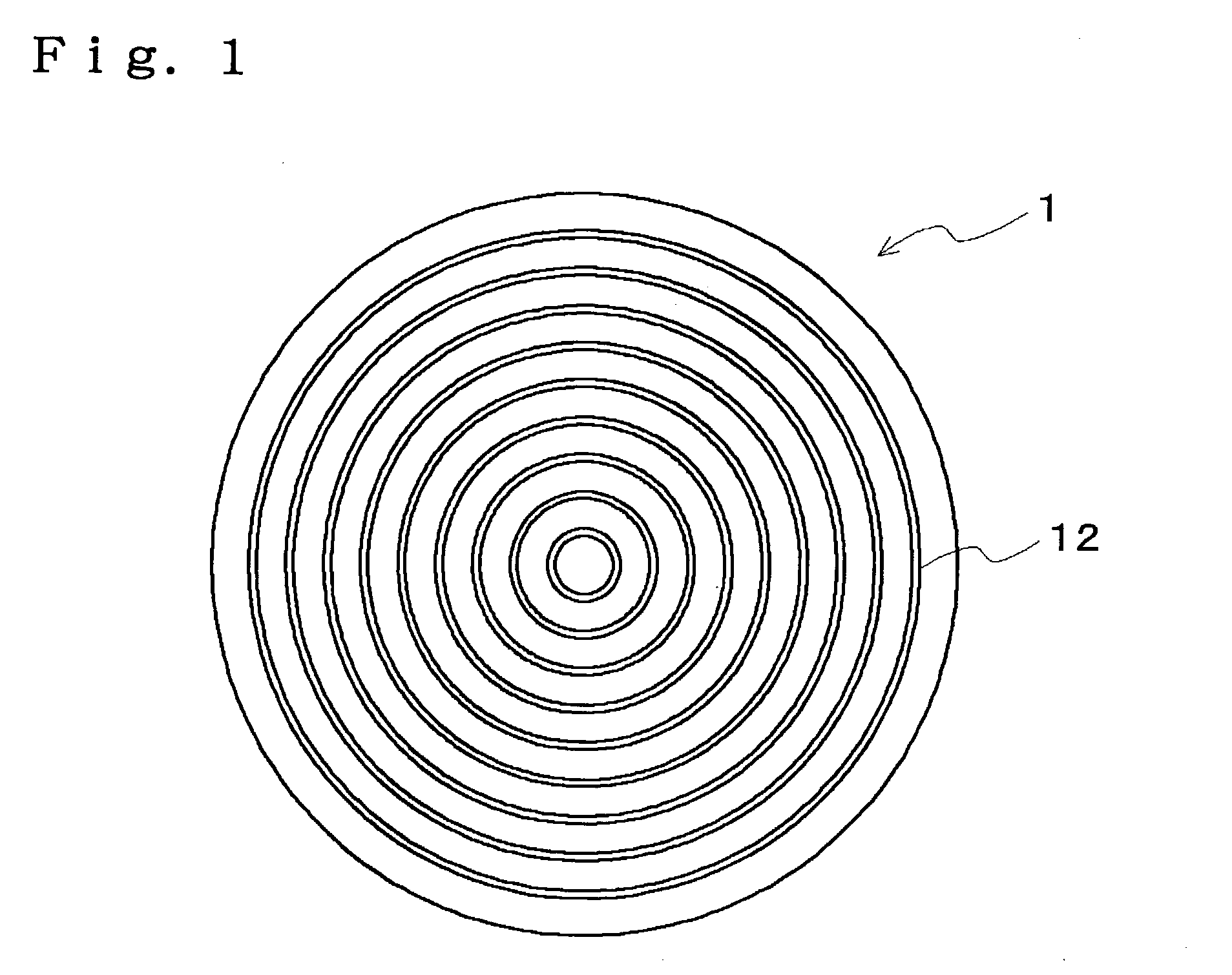
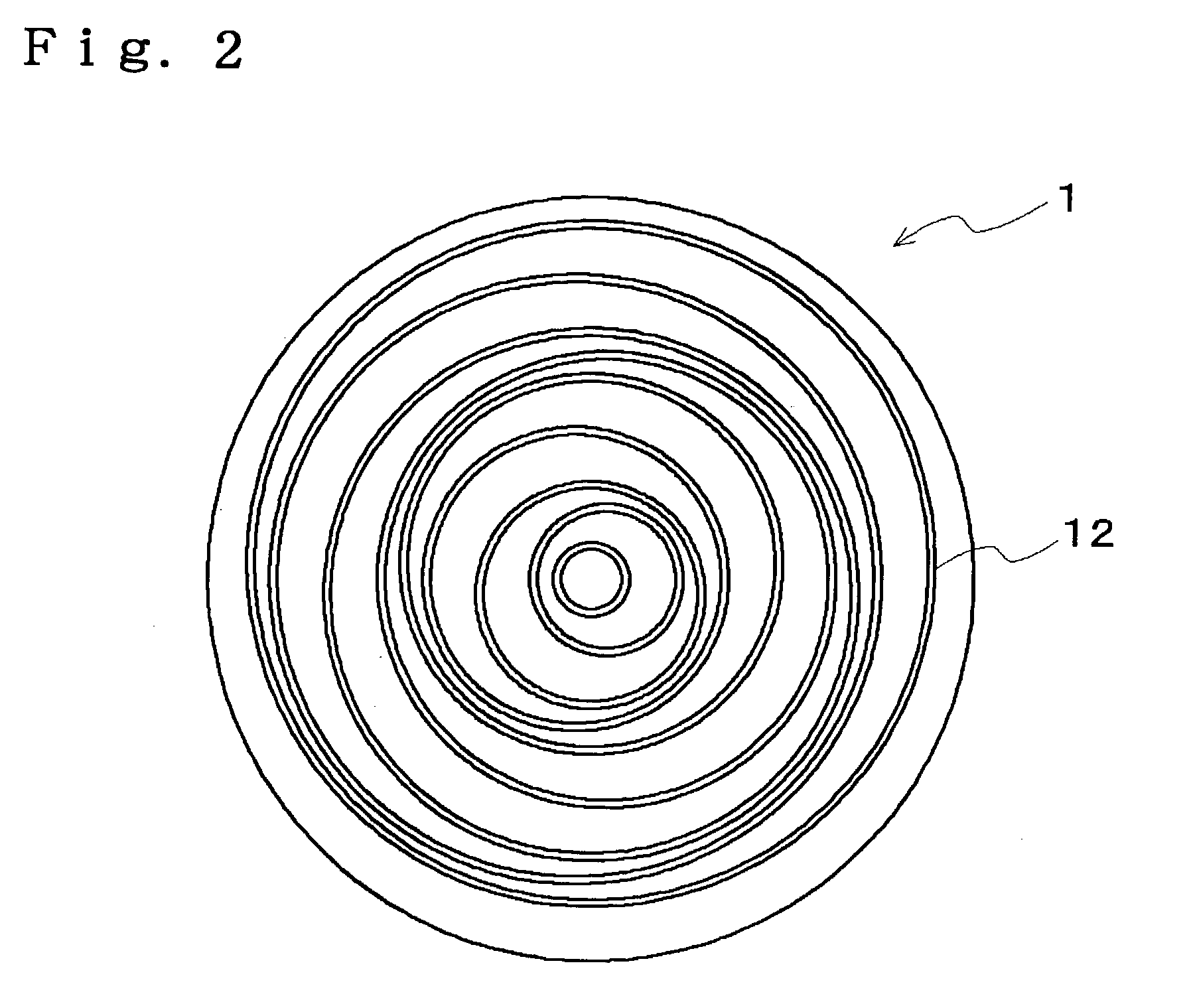
[0133] 80 parts by volume of 1,2-polybutadiene (Trade name "JSR RB830" manufactured by JSR Corp.) that becomes a water-insoluble matrix by crosslinking and 20 parts by volume of .beta.-cyclodextrin (Trade name "Dexipearl .beta.-100" manufactured by Bio Research Corporation of Yokohama, average particle diameter; 20 .mu.m) that as a water-soluble particle were kneaded with a screw extruder that is temperature-controlled at 160.degree. C., and thereby white pellet was obtained. Thereafter, 0.3 parts by volume of organic peroxide (Trade name "Percumyl D-40" manufactured by NOF Corp.) were compounded and further kneaded at 120.degree. C.; the kneaded material was extruded into a die and heated at 170.degree. C. for 18 minutes to crosslink; and thereby a disc-like molded body having a diameter of 60 cm and a thickness of 2.5 mm was obtained. Thereafter, concentric circle-like grooves in which a width is 0.5 mm, a depth is 1 mm, a pitch is 1.5 mm and a length between adjacent grooves is 1...

example 1-2

[0136] 100 parts by volume of 1,2-polybutadiene (Trade name "JSR RB840" manufactured by JSR Corp.) that becomes a water-insoluble matrix by crosslinking and 100 parts by volume of a water-soluble particle (average particle diameter: 20 .mu.m) obtained by coating polypeptide on .beta.-cyclodextrin (Trade name "Dexipearl .beta.-100" manufactured by Bio Research Corporation of Yokohama) were kneaded with a screw extruder that is temperature-controlled at 160.degree. C., and thereby white pellet was obtained. Thereafter, 0.3 parts by volume of organic peroxide (Trade name "Perhexine 25B" manufactured by NOF Corp.) were compounded with the white pellet and further kneaded at 120.degree. C., and thereby white pellet was obtained. In the next place, the organic peroxide-added white pellet was introduced into a die and heated at 190.degree. C. for 10 minutes to crosslink; and thereby a disc-like molded body having a diameter of 60 cm and a thickness of 2.5 mm was obtained. Thereafter, on on...

example 2-1

[0153] On one surface side of the disc-like molded body that was obtained in Example 1-1 and had a diameter of 60 cm and a thickness of 2.5 mm, lattice-like grooves in which a width is 0.5 mm, a depth is 1 mm, a longitudinal pitch is 5 mm and a transverse pitch is 5 mm, and a planar shape of one pattern that forms a lattice is a square shown in FIG. 4 were formed with a cutting machine manufactured by Kato Kikai Co., Ltd.

[0154] In the next place, from the obtained polishing pad, a slice for use in surface roughness measurement was cut so that a groove might be included in a width direction. Thereafter, the surface roughness Ra of an inner surface of the groove was measured in three different view fields of the slice with the above-mentioned three-dimensional surface structure analytic microscope. As a result, the surface roughness Ra was 2.5 .mu.m.

[0155] A section of a part of the groove for the polishing pad was enlarged and observed with an optical microscope. The obtained microgr...


PUM


Abstract

The present invention intends to provide a polishing pad and a multi-layer polishing pad that can particularly effectively suppress scratch from occurring. The polishing pad of the invention comprises at least one part selected from a groove (a) having at least one kind of shape selected from annular, lattice-like and spiral form on a polishing surface side, a concave portion (b) and a through hole (c). In the above, surface roughness of an inner surface of the part is 20 mum or less and the polishing pad is used for chemical mechanical polishing.

Description

[0001] 1. Field of the Invention[0002] The present invention relates to a polishing pad and a multi-layer polishing pad. In more detail, the invention relates to a polishing pad and a multi-layer polishing pad that have a groove having a specific shape on a polishing surface side, or a concave part having a specific shape that opens toward a polishing surface side. The polishing pad and the multi-layer polishing pad of the invention can be widely used in manufacture of semiconductor devices, and particularly preferably used in chemical mechanical polishing and the like of a surface of a material to be polished such as a wafer.[0003] 2. Description of the Prior Art[0004] Recently, chemical mechanical polishing (CMP) attracts attention as a polishing method that allows forming a surface having excellent planarity. In the CMP, with a polishing pad and a surface to be polished of a material to be polished sliding, a slurry that is an aqueous dispersion therein abrasive is dispersed is f...

Claims


Application Information

Patent Timeline
IPC IPC(8): B24B37/26B24D13/12B24D13/14
CPCB24B37/26H01L21/304
Inventor KAWAHASHI, NOBUOHASEGAWA, KOUSHIHO, HIROSHIKOUMURA, TOMOOKAWAHARA, KOUJIHOSAKA, YUKIO
Owner JSR CORPORATIOON
Why Eureka
Try Eureka