Microlithographic reduction projection catadioptric objective

a technology of reduction projection and catadioptric objective, which is applied in the direction of instruments, electrical appliances, basic electric elements, etc., can solve the problems of low numerical aperture and offers similar mounting and adjustment difficulties, substantive delays in the development of lithography tools for the most extreme vuv wavelengths, and difficulty in reducing the number of lithographic reduction projections. achieve the effect of improving performance, improving pupil aberration control, and increasing freedom

Inactive Publication Date: 2004-02-12
MASCHFAB KEMPER
View PDF10 Cites 16 Cited by
  • Summary
  • Abstract
  • Description
  • Claims
  • Application Information

AI Technical Summary

Benefits of technology

0041] More axial chromatic aberration and Petzval curvature may be included over that of the front end of FIG. 1, by increasing the power of the negative lens L2 near the concave mirror M1. A strong lens L2 , however, may tend to put in more overcorrected spherical aberration than is desired, making the intermediate image aberrations be larger than desired. In view of this, a preferred alternative to the design shown in FIG. 1 includes two concave lenses near the concave mirror

Problems solved by technology

In addition, all but one of the six mirrors shown at FIG. 3 are cut off sections of bodies of revolution, yielding mounting and adjustment face difficulties.
The objective described in the '035 application also exhibits a low numerical aperture and offers similar mounting and adjustment difficulties as described above with respect to the '528 application.
As optical lithography is extended into the vacuum ultraviolet (VUV), issues surrounding the laser linewidth and material availability could cause substantive delays to the development of lithography tools for the most extreme VUV wavelengths.
However,these systems have a serious drawback since the size of this beam splitting element becomes quite large as the numerical aperture is increased up to and beyond 0.65 to 0.70, making the procurement of bulk optical material with sufficient quality (in three-dimensions) a high risk endeavor.
This problem is exacerbated as wavelengths are driven below 193 rm because the selectio

Method used


Image

  • Microlithographic reduction projection catadioptric objective
  • Microlithographic reduction projection catadioptric objective
  • Microlithographic reduction projection catadioptric objective

Examples


Embodiment Construction

Parameter Performance Wavelength (nm) 157 Bandwidth (pm) 0.5 Reduction ratio (R) 0.20 Field size (mm) 26 .times. 7 Numerical aperture (NA) 0.75 RMS wavefront error (waves) 0.0057 Distortion (nm) <0.5 nm Paraxial Axial Color 25.0 Paraxial Lateral Color 0.0 Total track (mm) 1172.2 Front working distance (mm) 25.2 Back working distance (mm) 6.30

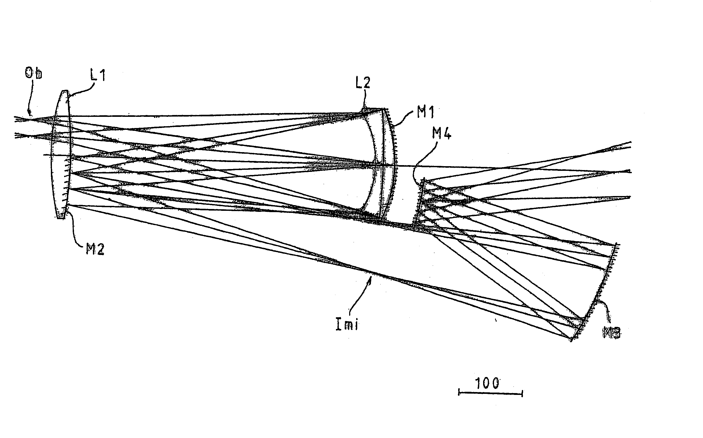
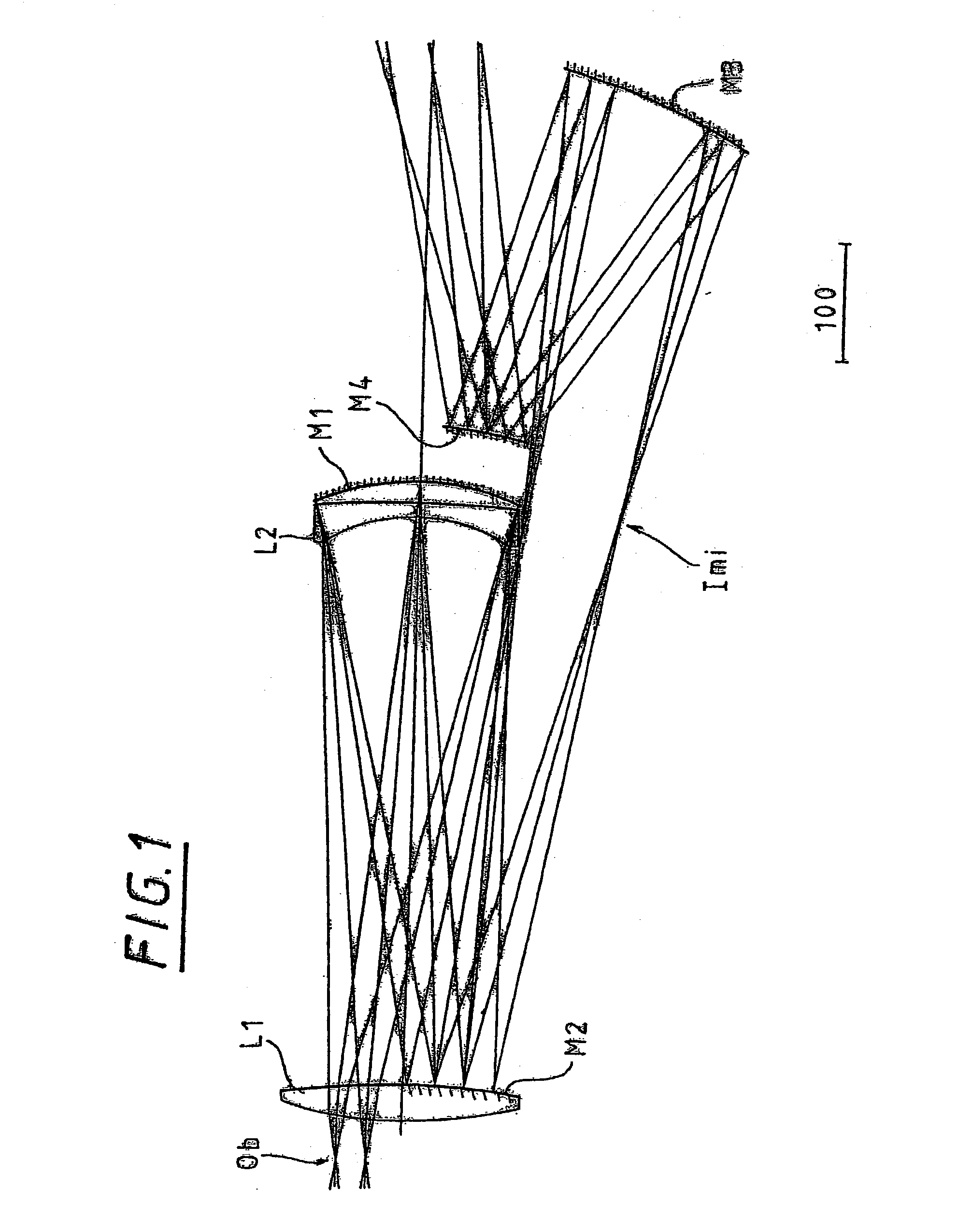
[0064] Lens element E1 provides for the telecentric condition at the plane of the mask. It is advantageous to have positive optical power near the mask to reduce the chief ray height on mirror M1. Lens element E1 appears to lie in conflict with the substrate of mirror M2. To achieve this concept in practice, only a small off-axis section of E1 would be used. This means that pieces of a complete E1 could be sectioned to yield pieces for multiple projection systems, further reducing the required blank mass of a single system. Another option to resolve the apparent conflict between E1 and the substrate of M2 is to place E1 between M1 and M2, somewh...


PUM


Abstract

A photolithographic reduction projection catadioptric objective includes a first optical group having an even number of at least four mirrors and having a positive overall magnifying power, and a second substantially refractive optical group more image forward than the first optical group having a number of lenses. The second optical group has a negative overall magnifying power for providing image reduction. The first optical group provides compensative aberrative correction for the second optical group. The objective forms an image with a numerical aperture of at least substantially 0.65, and preferably greater than 0.70 or still more preferably greater than 0.75.

Description

[0001] This application is a divisional of U.S. patent application Ser. No. 09 / 761,562, filed Jan. 16, 2001, which claims the benefit of U.S. patent application serial No. 60 / 176,190, filed Jan. 14, 2000, both of which are hereby incorporated by reference in their entirety.[0002] 1. Field of the Invention[0003] The invention relates to a microlithographic reduction projection catadioptric objective, and particularly including an even number of four or more mirrors and an unobscured aperture, and excluding any planar folding mirrors.[0004] 2. Description of the Related Art[0005] Microlithogrphic reduction projection catadioptric objectives, such that shown and described with respect to FIG. 3 of European patent no. EP 0 779 528 A2, are known as variants of pure catoptric objectives. FIG. 3 of the '528 application shows a system having six mirrors and three lenses. The optical surfaces are generally symmetric to a common axis upstream and downstream of the objective, respectively. As ...

Claims


Application Information

Patent Timeline
IPC IPC(8): G02B17/08G03F7/20H01L21/027
CPCG02B13/22G02B17/0828G02B17/0844G03F7/70358G02B17/0892G03F7/70225G03F7/70275G02B17/0848
Inventor SHAFER, DAVID R.HUDYMA, RUSSELLULRICH, WILHELM
Owner MASCHFAB KEMPER
Why Eureka
Try Eureka