Well treatment apparatus and method

a technology for treating equipment and wells, applied in the direction of surveying, sealing/packing, borehole/well accessories, etc., can solve the problems of unavoidable problems, limitations and disadvantages, and cannot be brought to the earth's surface withou

Inactive Publication Date: 2004-03-04
HALLIBURTON ENERGY SERVICES INC
View PDF38 Cites 208 Cited by
  • Summary
  • Abstract
  • Description
  • Claims
  • Application Information

AI Technical Summary

Benefits of technology

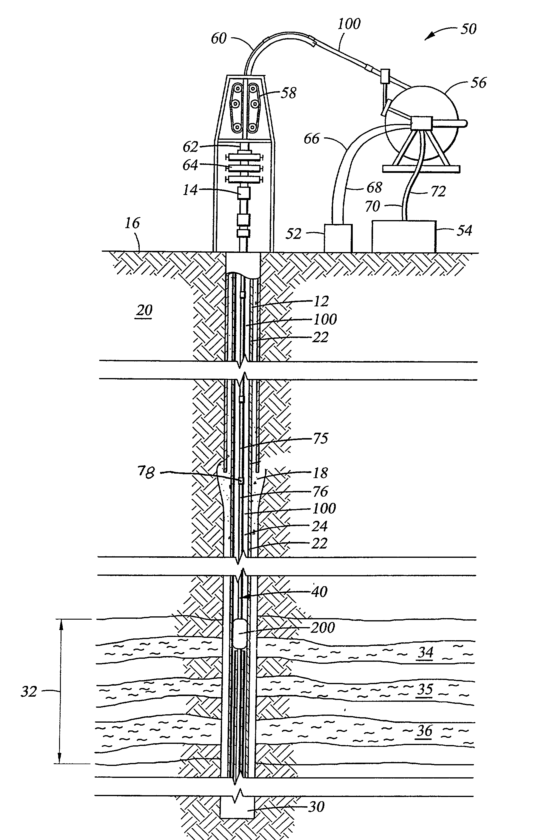
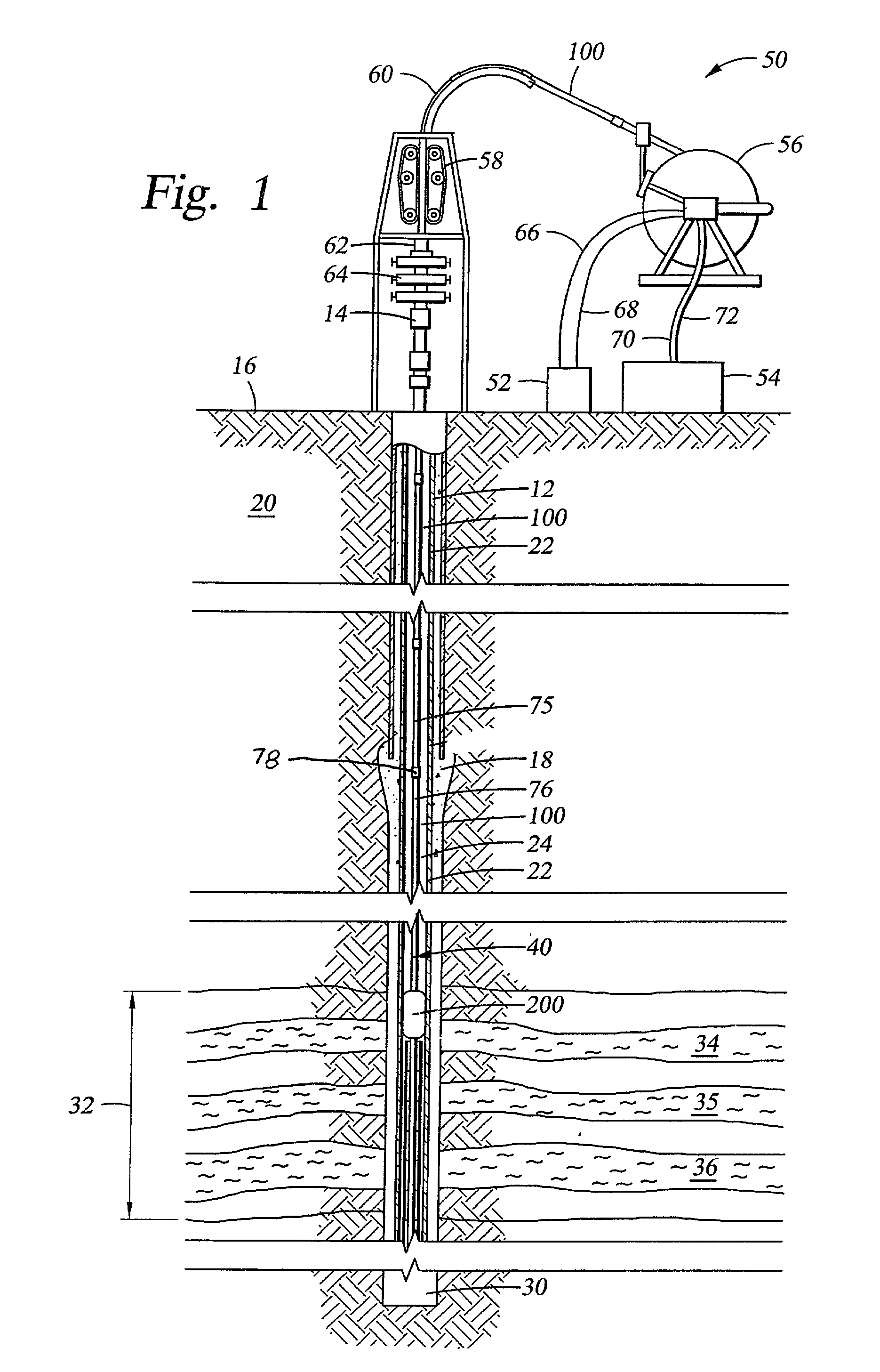
[0028] Accordingly, there is provided herein apparatus and methods enabling multiple zones within a formation to be treated sequentially with a single trip of the work string and which, in certain embodiments, provide transmission of power and transmission of data indicative of actual wellbore conditions for enhanced safety and system reliability.
[0031] To isolate the appropriate well interval to be treated, it is preferred that the bottom hole assembly include one or more packers and a packer actuator associated with each packer for causing the packer to expand and isolate a well interval in response to an electrical signal transmitted from the surface to the bottom hole assembly via the conductors. The conductors supported by the tubing string provide two way communication between the surface and the bottom hole assembly, as well as a means for transmitting electrical power from the surface to the bottom hole assembly. Further, given this direct communication link from the bottom hole assembly to the surface, real time well data may be sensed and communicated to the surface controller enabling adjustments to the treatment operation to be performed, both to enhance the effectiveness of the operation and to provide a means to determine downhole conditions accurately, such as pressure, and, when required, to throttle back or shut down pumping equipment before any dangerous situation develops.
[0032] In another preferred apparatus, the bottomhole assembly includes a detector sub having a sensor that detects anomalies in the casing, such as perforations and casing joints. Such a detector communicates the sensed data to the surface via the conductors supported by the tubing string so that the bottom hole assembly can be appropriately positioned. More specifically, the detector permits the packers to be set in blank sections of casing so as to properly isolate a particular well interval so that the fluids pumped downhole can penetrate into the intended zone via the perforations, and so that the packers are not eroded or washed out due to improper packer placement within a casing anomaly.
[0035] The preferred embodiments summarized above thus permit multiple zones within a given formation to be treated sequentially, with a single trip of the well treatment work string. Given the real time communication link provided via conductors, either embedded in the wall of the tubing string or supported by other means along the length of the tubing or pipe, real time communications of important downhole conditions can be communicated to the surface, enabling the surface controller and operator to avoid dangerous conditions and better tailor the treatment operation, such as by varying the density or makeup of the fluid being pumped downhole.

Problems solved by technology

If a formation's porosity is low, meaning that the pores are not sufficiently interconnected, the fluids cannot migrate through the formation and, thus, cannot be brought to the earth's surface without a structural modification or stimulation of the production zone.
This previously proposed perforation and proppant fracturing technique has several well known and heretofore unavoidable problems, limitations and disadvantages.
For example, when the proppant slurry discharge member is lowered into the well bore, it is difficult to obtain a precise alignment (in both the axial and angular directions) between the discharge ports in the discharge member and the perforations in the casing.
The usual result is that some degree of misalignment exists between the discharge ports and the perforations.
Because of the highly abrasive character of proppant slurry and because the slurry is under very high pressure, this tortuous flow path can cause severe abrasion and wear with respect to the components of the bottom hole assembly and to the casing.
Use of the above-described prior technique also limits the ability to isolate multiple production zones from one another--a requirement that may be necessary due to the fact that different zones may require different fracturing pressures, different types of fracturing fluids, and different amounts of proppant.
In many such operations, however, the results were not satisfactory.
Thus, because little fracing fluid actually enters the other zones when this occurs, certain potentially productive zones are not adequately stimulated or fraced, and do not thereafter produce to the desire degree.
The method thus described, however, has inherent limitations.
Turbulence caused by the abrasive fracing fluid flowing back into the annulus creates a pressure differential across the packers and tends to erode or "wash out" and ruin the packer assembly, an event that frustrates the fracturing operation.
If the packers are set on those gaps, then the packers will not seal properly and hold pressure to isolate the intended interval.
This condition can cause the packers to wash out and erode.
Further, depositing large quantities of proppant above the packer assembly may cause the assembly to stick in the hole or to otherwise become difficult to relocate.
Unfortunately, properly positioning the packers with respect to the perforations and casing joints has been difficult to achieve.
For deep wells, depth control is more problematic.
For example, if the work string is jointed pipe, the weight of the work string extending into a deep well tends to cause the string to stretch such that its length, and thus the location of the downhole tool it supports, may not provide an accurate depth indication.
Further, the work string will tend to expand and contract with downhole temperatures which also introduces inaccuracies in the length of the string and thus the actual depth of the tools.
In another example, when the workstring is coiled tubing and it is run into a deep well, it tends to bend and curl within the cased borehole, such that the exact distance from the surface to the downhole tool does not equal the length of coiled tubing that has been injected into the well.
Using closely-spaced straddle packers in a deep well however, and considering the expansion and contraction of the coiled tubing, as well as the tendency for the coiled tubing to bend and curl in the borehole, it is extremely difficult to determine exactly where the packers and fracing assembly are in relation to casing joints and the perforations.
Although conventional metal coiled tubing has been employed in shallow wells in certain fracing operations, it is not feasible in certain deep wells.
For example, most conventional metal coiled tubing cannot withstand a 12,000 psi differential pressure as may be encountered at the surface when conducting deep well fracing operations.
Further, metal coiled tubing is relatively heavy and transporting the number of spools of coiled tubing required for the operation and injecting and withdrawing the tubing from a deep well requires specially designed, heavy duty equipment
Furthermore, even if the depth of the fracing assembly were somehow to be precisely known, there still exist problems that are introduced due to inaccuracies in determining the actual depth of the perforations.
As stated above, the step of perforating the well typically includes recording the depth and location of the perforations; however, using perforation equipment with wire line, jointed pipes and coiled tubing nevertheless does not always provide accurate depth measurements, due again to the tendency of the wireline, pipe and tubing to expand with weight and downhole temperatures, and to bend or coil in the borehole.
Another problem inherent in fracing operations in deep wells raises significant safety concerns.
When screen out occurs without warning, a potentially hazardous condition is created at the surface where the fracing fluid is continuing to be pumped through the work string at very high pressures, such as from 5,000 to 18,000 psi.
When the downhole pressure suddenly spikes, the differential pressure as measured across the wall of the work string at the surface may exceed the margin of safety causing the pipe to burst, subjecting personnel and equipment to risk.
Positioning a pressure sensor in the workstring adjacent to the discharge sub to sense downhole pressure and communicate the pressure data to the operator or controller at the surface would be advantageous; however, communicating data to the surface during fracing operations has presented a problem.
Although it is common to use mud pulse telemetry in well operations for transmitting data to a surface controller, mud pulse telemetry is difficult if not impossible to employ in fracing operations because there is too much hydrostatic noise which prevents transmission of telemetry up the annulus to the surface.
Further, although electrical signals can be sent uphole via conductors strapped on the outside of the work string, the conductors are subjected to abuse and damage as the work string scraps against the sides of the well bore while the workstring is lowered into or removed from the bottom of the wellbore, and as well fluids flow around the conductors.
However, for several reasons, it is extremely difficult to extrapolate the downhole pressure from the measured surface pressure and the other available data, particularly in deep well operations.
Thus, the weight of fluid being pumped downhole increases as the process continues over time.
These changing variables, coupled with the high volume of fluid that is pumped during the fracing operation, makes calculating the downhole pressure very complex.
The fluids and their density change so fast that it is difficult if not impossible to calculate accurately downhole pressure.
Once again, if the downhole pressure spikes quickly and the spike cannot be seen or predicted soon enough based on the pressures calculated at the surface, the excessive pressure can cause the work string to burst, endangering both crew and equipment.
The fact that the fracing fluid is in two phases and that the volume of gas changes continuously as the fluid moves down into the well bore also makes it even more difficult to calculate bottom hole pressure.
Unfortunately, when the fracing operation includes pumping proppant downhole, this prior method of employing a wire line communication link is not believed to be viable because of erosion to the conductors that occurs at the well head where the proppant is injected, and because of the danger of proppant building-up around the downhole tilt sensors which might cause the downhole assembly to become stuck.

Method used


Image

  • Well treatment apparatus and method
  • Well treatment apparatus and method
  • Well treatment apparatus and method

Examples


Embodiment Construction

[0028] Accordingly, there is provided herein apparatus and methods enabling multiple zones within a formation to be treated sequentially with a single trip of the work string and which, in certain embodiments, provide transmission of power and transmission of data indicative of actual wellbore conditions for enhanced safety and system reliability.

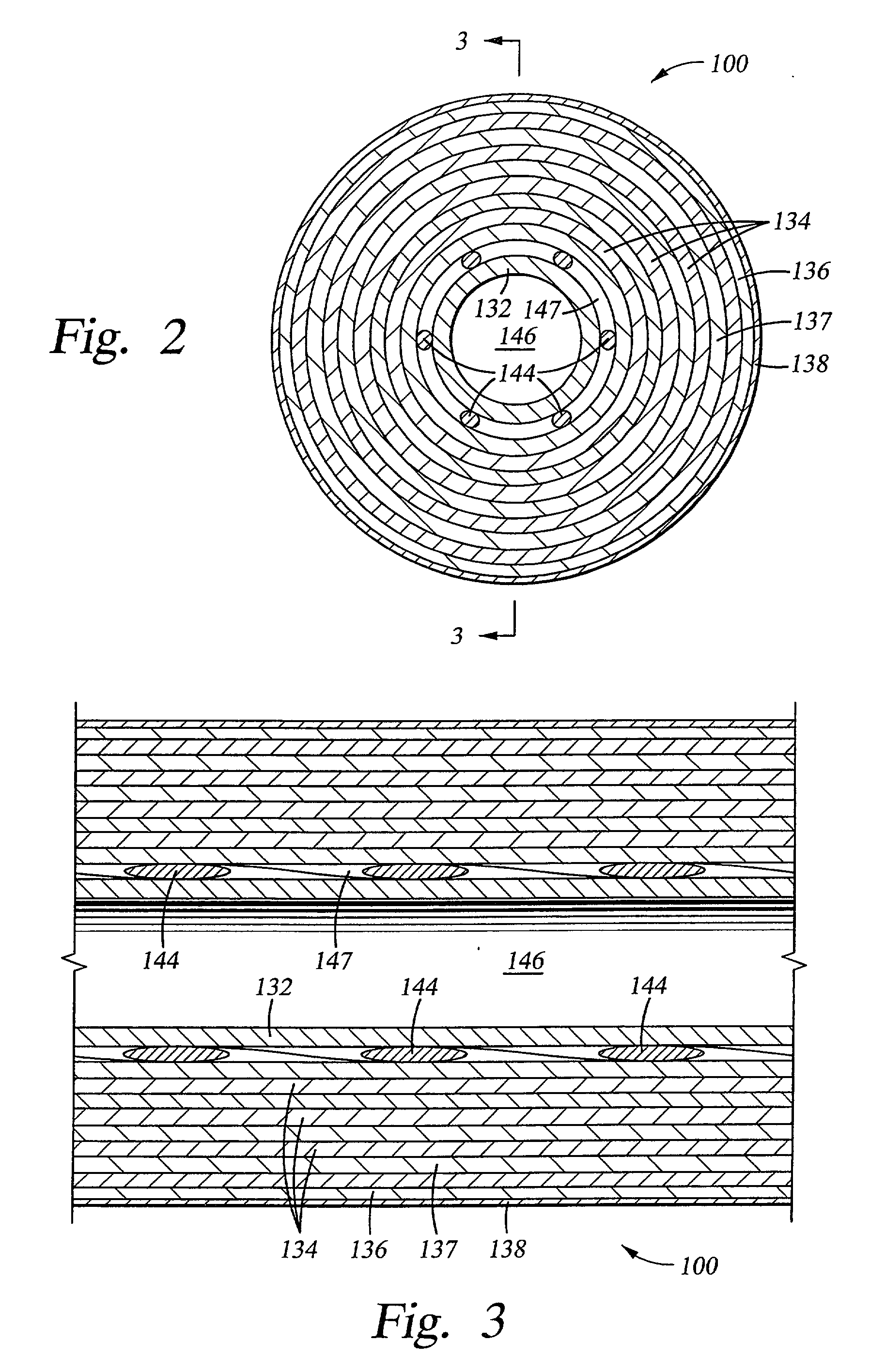
[0029] A preferred apparatus includes a bottom hole assembly having a tubular, ported sub and a tubing string connected to the bottom hole assembly. The tubing string and bottom hole assembly include fluid passageways that are in fluid communication so that treatment fluids may be pumped from the surface through the tubing string and out of the ports in the tubular sub when positioned adjacent to the zone to be treated. Preferably, the tubing string is a composite tubing having conductors embedded in the walls of the tubing and extending from the bottom hole assembly to the surface. Alternatively, metal tubing or jointed pipe may be employe...


PUM


Abstract

Apparatus and methods are disclosed for sequentially treating multiple zones in underground formation in a single trip of the well treatment work string. In the one embodiment, the work string includes composite tubing having electrical conductors embedded within the walls, the conductors enabling power transmission and two way communication between the surface and the sensor or detectors downhole so that real time data can be sensed and communicated. Isolation packers are actuated via electrical signals from the surface communicated to the bottom hole assembly via the conductors. A detector located in the bottom hole assembly may be provided to detect perforations or other anomalies in the casing, such as joints, enabling the surface controller to position packers properly in blank segments of casing so that well intervals can be properly isolated and the adjacent formation effectively treated.

Description

[0001] Not Applicable.[0002] Not Applicable.[0003] 1. General Field of the Invention[0004] The present invention relates generally to tools and methods used in treating subterranean wells and, in a preferred embodiment thereof, relates more particularly to apparatus and methods for conducting well stimulation and formation fracturing operations in subterranean wells.[0005] 2. Background Information[0006] A potentially productive geological formation beneath the earth's surface often contains a sufficient volume of valuable fluids, such as hydrocarbons, but also may be characterized as having a very low permeability. "Permeability" is a term relating to a quality of a geological formation which describes the ability of fluids to move about through the formation. The hydrocarbons are contained in the formation's pores, and a formation may be described in terms of its "porosity." If a formation's porosity is low, meaning that the pores are not sufficiently interconnected, the fluids ca...

Claims


Application Information

Patent Timeline
Patent Type & Authority Applications(United States)
IPC IPC(8): E21B17/20E21B23/06E21B33/124E21B43/14E21B43/267E21B47/01E21B47/06
CPCE21B17/206E21B23/06E21B33/124E21B47/06E21B43/267E21B47/01E21B43/14
Inventor DUSTERHOFT, RONALD G.VACLAVIK, RICHARDLAURSEN, PATRICKESTEP, JAMESSONG, HAOSHIPAULK, MARTIN D.TERRY, JAMES
Owner HALLIBURTON ENERGY SERVICES INC
Why Eureka
Try Eureka