Carbon nanotube array and method for forming same

a carbon nanotube and array technology, applied in the direction of polycrystalline material growth, crystal growth process, transportation and packaging, etc., can solve the problems of complex purification process, low yield of vaporization method, and inability to meet the requirements of vaporization method

Active Publication Date: 2004-03-18
HON HAI PRECISION IND CO LTD +1
View PDF6 Cites 73 Cited by
  • Summary
  • Abstract
  • Description
  • Claims
  • Application Information

AI Technical Summary

Problems solved by technology

The arc discharge and laser vaporization methods are not able to satisfactorily control the diameter or length of the carbon nanotubes formed, and the yield of these methods is relatively low.
Moreover, excess a...

Method used


Image

  • Carbon nanotube array and method for forming same
  • Carbon nanotube array and method for forming same
  • Carbon nanotube array and method for forming same

Examples


Embodiment Construction

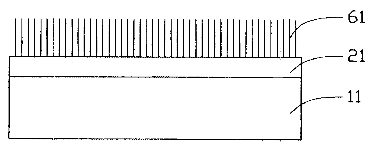
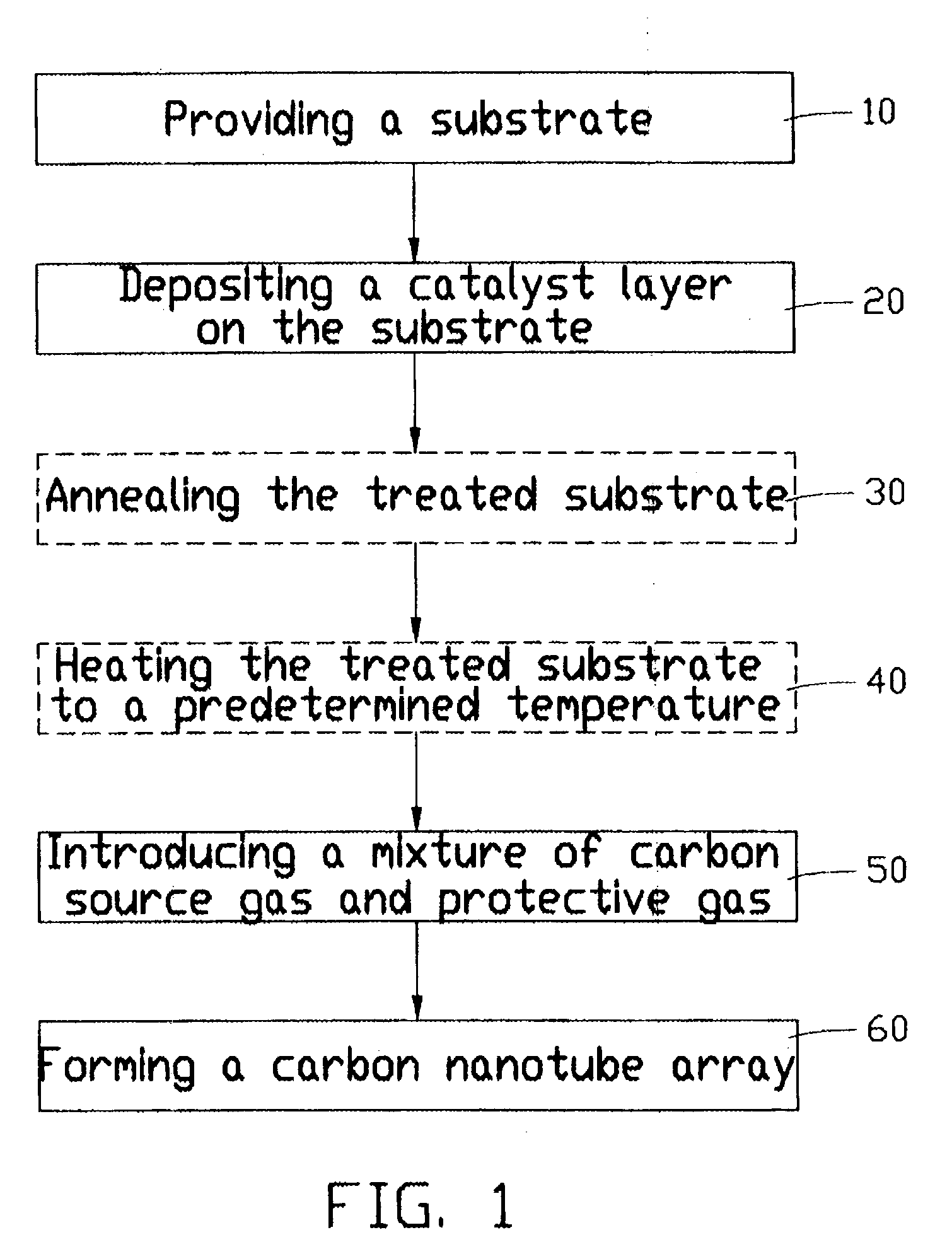
[0021] A preferred method of forming a carbon nanotube array according to the present invention will be described with reference to the flowchart of FIG. 1. In the flowchart, essential steps for forming the carbon nanotube array are shown in solid-line boxes, while optional steps are shown in dashed-line boxes.

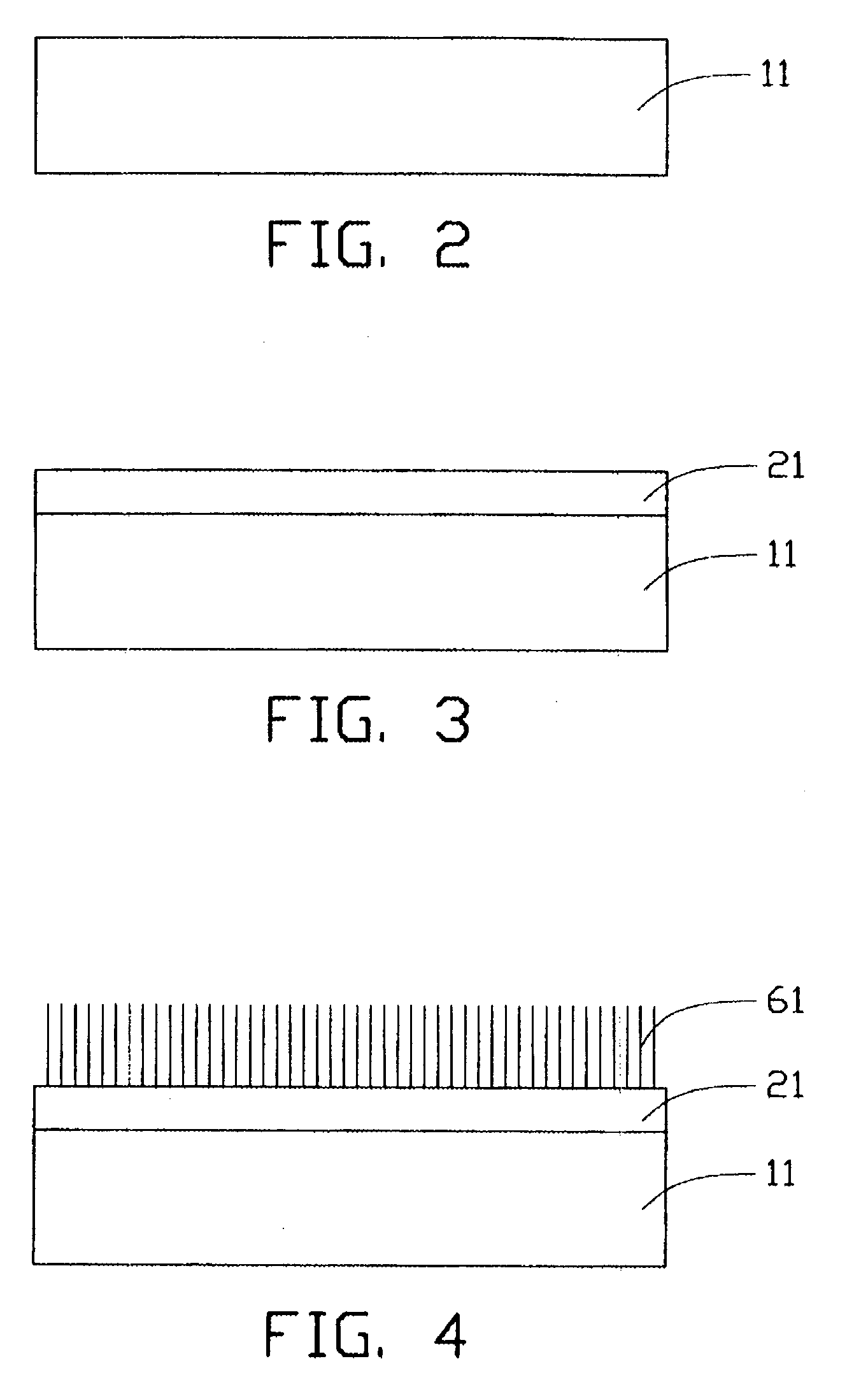
[0022] Referring also to FIGS. 2, 3 and 4, a smooth substrate 11 is first provided (step 10). The substrate 11 can be a P-type silicon wafer, an N-type silicon wafer, an intrinsic silicon wafer, or a silicon wafer with a film of silicon oxide thereon. In the preferred method, a P-type silicon (100) wafer with an 800 nm thick thermal-oxidized layer thereon is used as the substrate 11. The substrate 11 has a diameter of 2 inches and a thickness of 350 micrometers. The substrate 11 is polished to obtain a smooth surface thereon. A metal catalyst layer 21 is deposited on said surface of the substrate 11 by electron beam evaporation, thermal evaporation or sputtering. The catalyst ...


PUM

PropertyMeasurementUnit
Temperatureaaaaaaaaaa
Fractionaaaaaaaaaa
Fractionaaaaaaaaaa

Abstract

A method for forming a carbon nanotube array includes the following steps: providing a smooth substrate (11); depositing a metal catalyst layer (21) on a surface of the substrate; heating the treated substrate to a predetermined temperature in flowing protective gas; and introducing a mixture of carbon source gas and protective gas for 5-30 minutes, thus forming a carbon nanotube array (61) extending from the substrate. When the mixture of carbon source gas and protective gas is introduced, a temperature differential greater than 50° C. between the catalyst and its surrounding environment is created by adjusting a flow rate of the carbon source gas. Further, a partial pressure of the carbon source gas is maintained lower than 20%, by adjusting a ratio of the flow rates of the carbon source gas and the protective gas. The carbon nanotubes formed in the carbon nanotube array are well bundled.

Description

[0001] 1. Field of the Invention[0002] The present invention relates to a carbon nanotube array and a method for forming the same, and more particularly to a carbon nanotube array in which carbon nanotubes are well aligned and a method for forming the same.[0003] 2. Description of Prior Art[0004] Carbon nanotubes are very small tube-shaped structures having the composition of a graphite sheet rolled into a tube. Carbon nanotubes produced by arc discharge between graphite rods were first discovered and reported in an article by Sumio Iijima entitled "Helical Microtubules of Graphitic Carbon" (Nature, Vol. 354, Nov. 7, 1991, pp. 56-58).[0005] Carbon nanotubes are electrically conductive along their length, are chemically stable, and can have very small diameters (much less than 100 nanometers) and large aspect ratios (length / diameter). Due to these and other properties, it has been suggested that carbon nanotubes can play an important role in fields such as microscopic electronics, ma...

Claims


Application Information

Patent Timeline
IPC IPC(8): C01B31/02C23C16/02C23C16/26C30B25/00
CPCB82Y30/00C23C16/0281C23C16/26C30B25/00Y10T428/30Y10S977/843C30B29/02C30B29/605H01L23/373H01L2924/0002H01L2924/00
Inventor JIANG, KAILIFAN, SHOUSHANLI, QUNQING
Owner HON HAI PRECISION IND CO LTD
Why Eureka
Try Eureka