Method for accelerated bondline curing

a bondline and curing technology, applied in the direction of adhesive types, ohmic resistance heating, chemistry apparatus and processes, etc., can solve the problems of increasing the time and equipment required for the proper curing of adhesives, increasing the cost of adhesives, and increasing the cost of manufacturing, so as to achieve the optimal joint properties, accelerate the curing of bondline adhesives, and improve the bond properties

Inactive Publication Date: 2004-03-25
THERMION SYST INT
View PDF18 Cites 32 Cited by
  • Summary
  • Abstract
  • Description
  • Claims
  • Application Information

AI Technical Summary

Benefits of technology

0011] The present invention provides a method for accelerating the curing of an adhesive at a bondline between surfaces to be bonded, which improves the bond properties. Specifically, the method comprises disposing or applying a heater at the bondline, wherein the heater comprises an electrically conductive fabric of minimal thickness to the joint. The heater when energized generates heat locally at the bondline and accelerates curing of bondline adhesives, thereby achieving optimum joint properties once the adhesive is cured.

Problems solved by technology

However, as these multi-component structures become bigger and more complex, the processes or methods presently used to build such structures using adhesives demand increased amounts of time and higher costs to the industry.
One area of difficulty with such designs lies in the time and equipment required for the adhesives to properly cure.
The disadvantages of such methods are numerous.
Specifically, the costs associated with accelerated curing of adhesives in ovens, particularly those related to the aerospace market, can be attributed to some or all of the following inefficiencies: wasted energy consumed by the oven structure and surroundings; wasted energy in heating the entire part; the capital expenditure for the oven itself; potential deformation of the component material, and periodic maintenance of the oven.
Induction methods incur high costs as well, although not always recurring.
Because no single coil design can perform satisfactory for every joining operation, the user must be able to select from several available designs.
In some instances, expensive systems offering interchangeable coil designs must be used.
In addition to the coil and frequency generator, the electromagnetic interference and radio-frequency interference ratio (EMI / RFI) shielding necessary for induction coil heating devices can add considerable cost to the machine.
In addition to the cost and inefficiencies associated with the use of ovens or induction methods, both have inherent deficiencies in heating flexibility and / or temperature control.
While an oven can be built to accommodate large structures, it does not have the flexibility to provide discrete area heating.
A case in point would be a component previously installed within an assembly but which is not able to withstand the elevated temperatures necessary for the current curing cycle.
Nevertheless, the use of induction methods is limited by the necessity to be within a specific distance from the susceptor, a circumstance unlikely for complex geometries, not to mention the non-uniform field generated by such use.
Furthermore, some induction methods, for example, those outlined in U.S. Pat. No. 6,043,469 to Fink et al., U.S. Pat. No. 5,075,034 to Wanthal, and U.S. Pat. No. 6,056,844 to Guiles, require the introduction of materials within the bonding agent which, disadvantageously, are detrimental to the strength of the bond.
In a similar manner, Wanthal and Guiles depend on conductive particles within the thermoset adhesive used to produce the same result, each reducing the effective bond properties of the adhesives.
Bondline thicknesses of these magnitude are known to be detrimental to joint strength.

Method used


Image

  • Method for accelerated bondline curing
  • Method for accelerated bondline curing
  • Method for accelerated bondline curing

Examples


Embodiment Construction

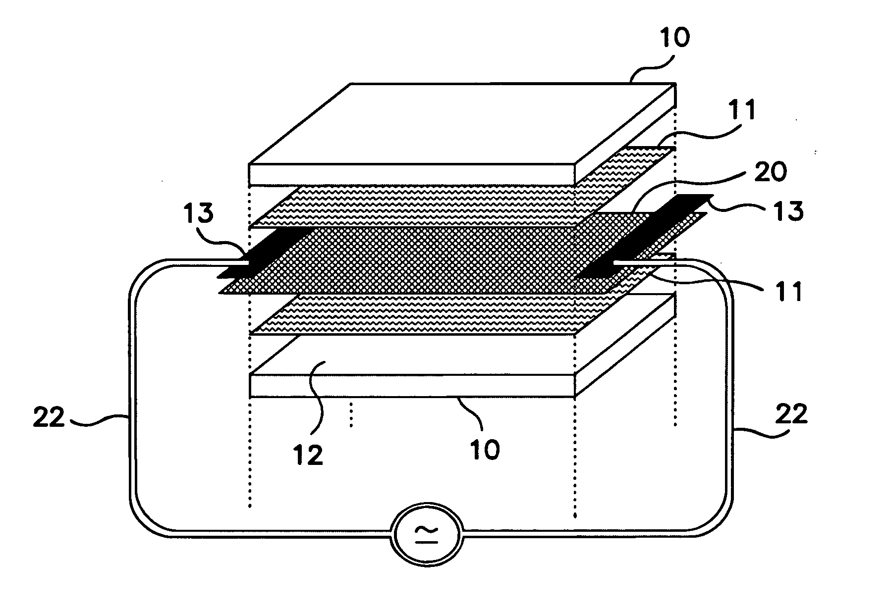
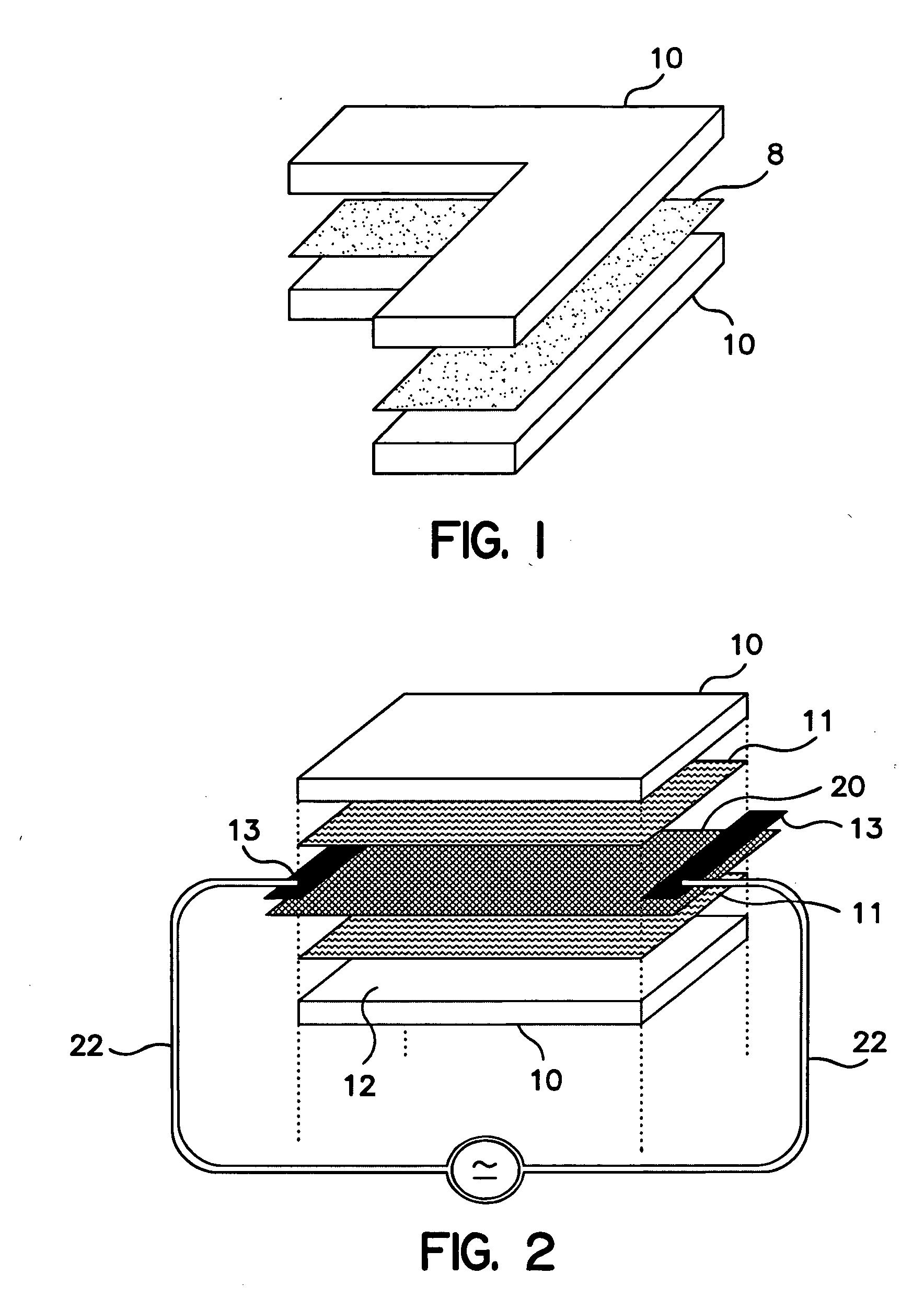
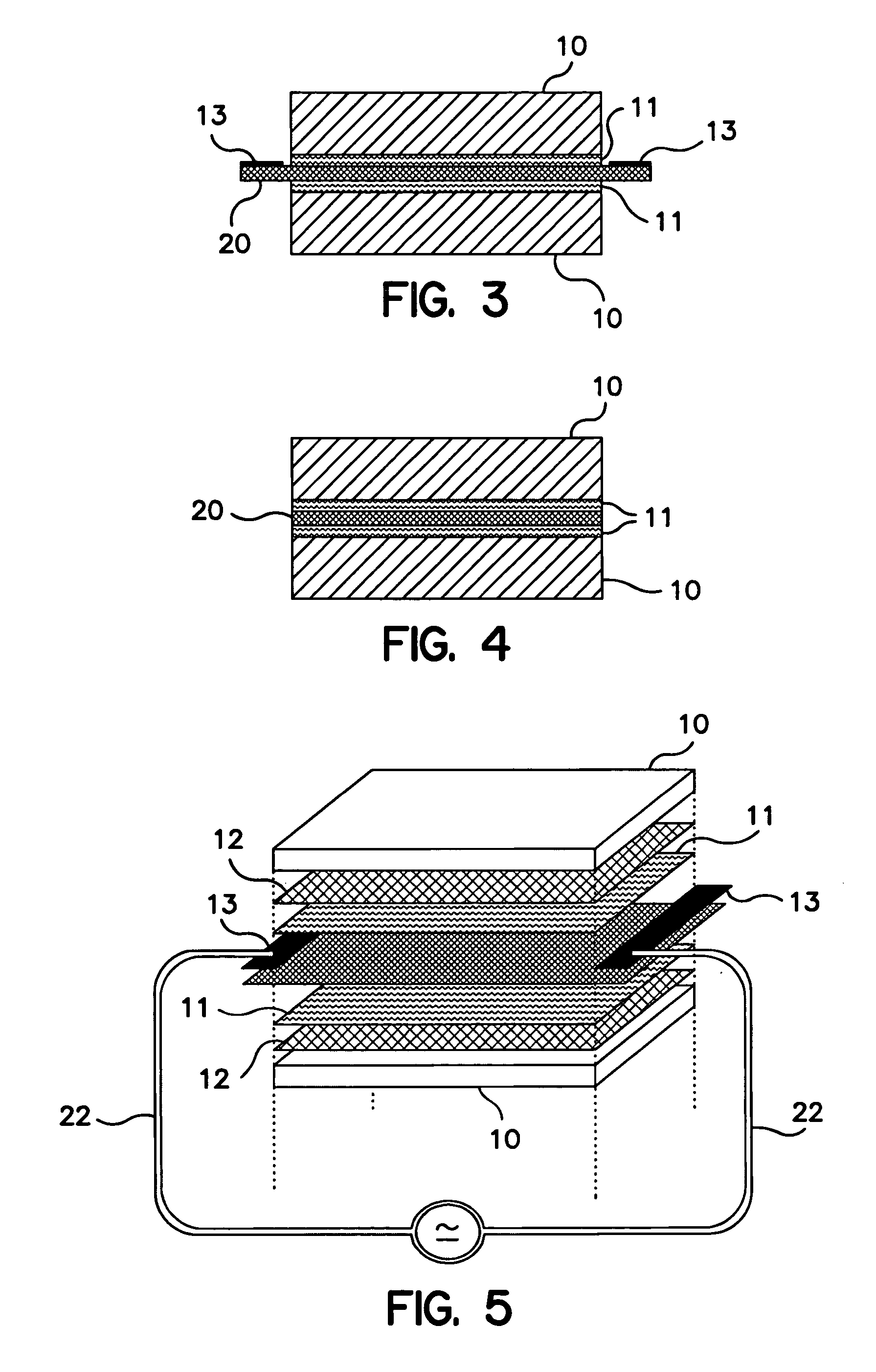
[0053] The following example illustrates a bonding process of the invention.

[0054] Two aluminum sheets of 0.125 inches in thickness, 15.0 inches in length, and 7.0 inches in width were treated with a dielectric primer on the bonding side surface and covered with a Cytec Fiberite FM94M 120.degree. C. cure epoxy film adhesive, cut to the same dimensions. A Thermion.RTM. fabric heater of 10 g / m2 non-woven, carbon fiber fabric coated with 7 g / m2 nickel and cut to 16.0 inches by 7.0 inches was sandwiched between the adhesive layers ensuring 0.5 inches of the heater fabric was exposed at each end as the two aluminum sheets were brought together. Copper foil bus bars of 0.002 inches thick by 7.0 inches long and 0.5 inches wide were laid across the exposed heater fabric, and the assembly was placed within a vacuum bag (not shown). The assembly was subjected to a voltage via a PID type temperature controller and power supply sufficient to raise the structure's temperature at a rate of 3.degr...


PUM

PropertyMeasurementUnit
thicknessesaaaaaaaaaa
thicknessaaaaaaaaaa
thicknessaaaaaaaaaa

Abstract

A method is provided for accelerating the curing of an adhesive at a bondline while bonding structures using a fabric heater. The method comprises applying an electrically conductive fabric heater between structures to be bonded to which a layer of adhesives is applied to the bonding surfaces of the structures. Once the adhesive layers and fabric heater are applied to the bondline, pressure is applied and the heater is energized to produce heat uniformly throughout the bondline at the curing temperature of the adhesive so that the adhesive is evenly or symmetrically cured. After curing the adhesive, the heater remains sandwiched at the bondline to act as a reinforcing fabric.

Description

[0001] This application claims the benefit of U.S. Provisional Patent Application No. 60 / 392,416, filed on Jun. 28, 2002.[0002] The invention relates to a method for accelerating the curing of an adhesive at a bondline for bonding structures. In accordance with the invention, a heater comprising an electrically conductive fabric is applied at a bondline between facing bonding surfaces layered with an adhesive, wherein the heater provides heat necessary to cure the adhesive to bond the surfaces together, and acts as a reinforcing layer when the curing / heating process is complete.BACKGROUND OF INVENTION[0003] The design and manufacturing of multi-component structures have increasingly relied upon the use of composites and, more specifically, the joining of component parts by adhesives as opposed to fasteners. Joining substrates or structures using adhesives has increased production throughput and allowed engineers to design larger and more complex parts. However, as these multi-compon...

Claims


Application Information

Patent Timeline
Patent Type & Authority Applications(United States)
IPC IPC(8): B29C65/34C09J5/06C09J163/00C09J167/00H01C17/065H05B3/34
CPCB29C65/344B29C66/962B29C65/3492B29C65/3496B29C65/4835B29C66/45C09J5/06H01C17/0652H05B3/342H05B2203/011H05B2203/013H05B2203/017H05B2203/033B29C66/91651B29C66/91221B29C66/91411B29C66/91443B29C66/91653B29C66/91655B29C65/3468B29C66/1122B29C66/71B29C66/73921B29C66/91216B29K2077/10
Inventor SMITH, FAYE C.GARDNER, ALAN D.MILLER, ANDREW J.
Owner THERMION SYST INT
Why Eureka
Try Eureka