Method of operating an internal combustion engine

a technology of internal combustion engine and working process, which is applied in the direction of combustion engine, machine/engine, mechanical apparatus, etc., can solve the problems of negative effects of longer cycle times, negative effects on emissions, and insufficient exhaust temperature, so as to achieve the lowest possible emissions, low loss of charge exchange, and high consumption potential

Inactive Publication Date: 2004-07-01
AVL LIST GMBH
View PDF2 Cites 30 Cited by
  • Summary
  • Abstract
  • Description
  • Claims
  • Application Information

AI Technical Summary

Benefits of technology

0029] The low loss in charge exchange and the combination of the two combustions SCSI and HCCI as well as the fact that this six-stroke working

Problems solved by technology

At low speed and load in particular, the exhaust temperature is no longer high enough to heat the charge to an extent sufficient to ensure auto-ignition, even if the amount of residual gas is extremely high.
Moreover, at low speed, the longer cycle times negatively af

Method used


Image

  • Method of operating an internal combustion engine
  • Method of operating an internal combustion engine

Examples


Embodiment Construction

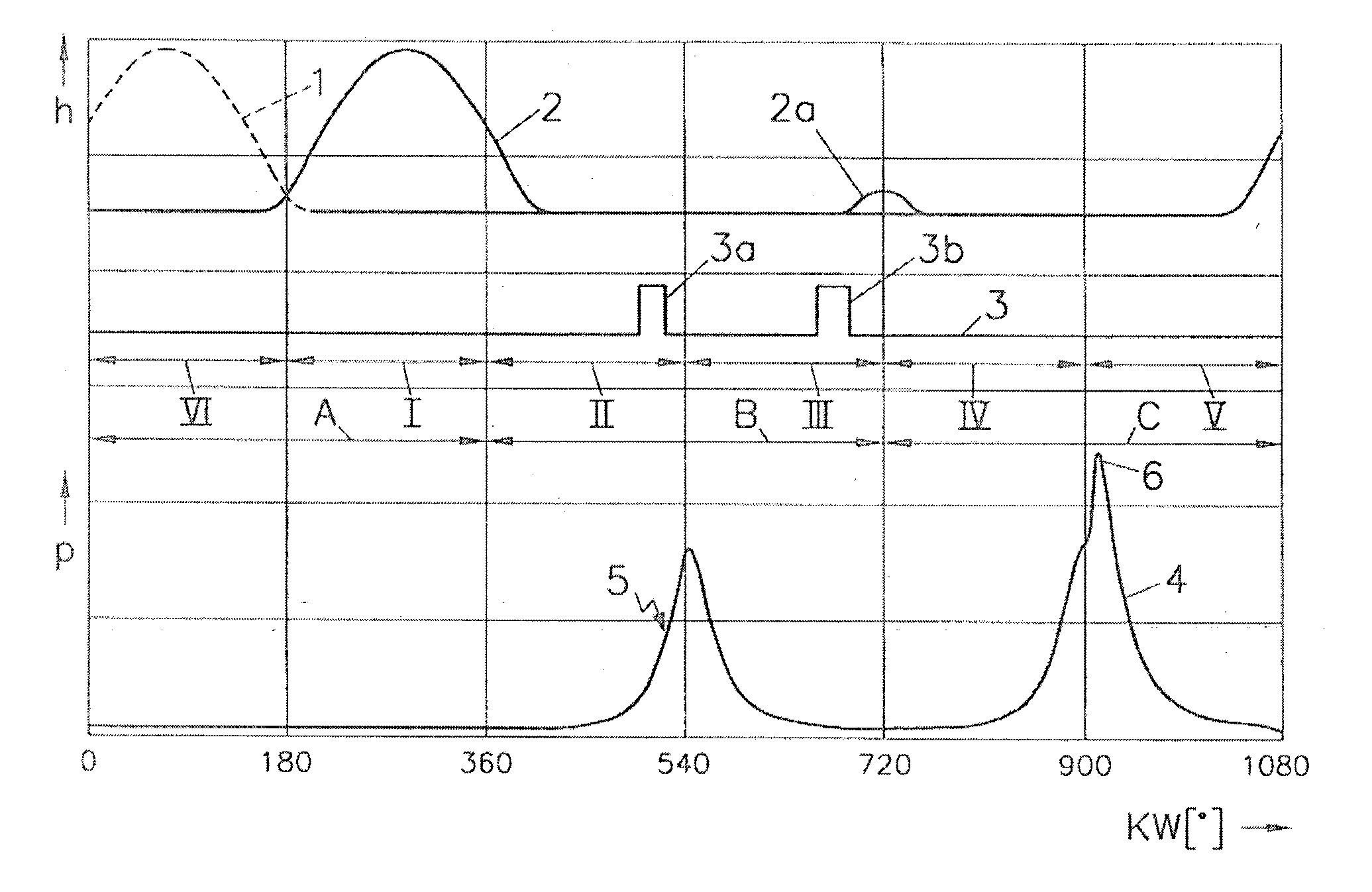
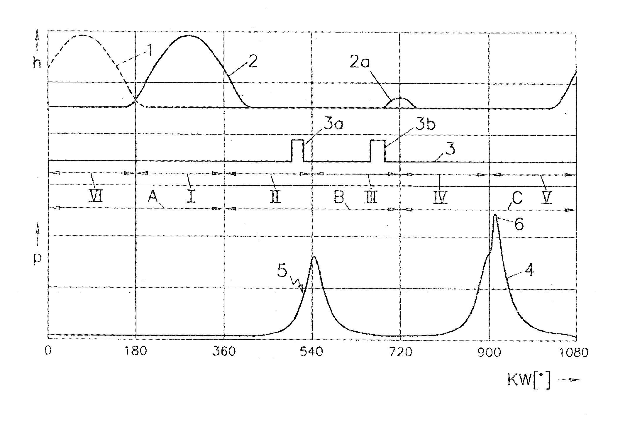
[0031] The FIGURE shows the valve lifts h of the exhaust valves and of the intake valves, the exhaust valve lift being indicated at 1 and the intake valve lift at 2.

[0032] Line 3 shows the injection events in the combustion chamber.

[0033] In the lower part of the diagram, the cylinder pressure p is plotted down the side thereof whereas the crank angle KW is plotted on the horizontal axis. This curve is indicated at 4.

[0034] The working method is comprised of six strokes I, II, III, IV, V, VI, two strokes pertaining to a respective one of a cycle A, B, C. The first cycle A serves for gas exchange and consists of stroke VI for exhaust expulsion and of stroke I for air intake. The second cycle B consists of stroke II during which the air is compressed inside the cylinder and a first fraction of gasoline fuel is injected and of stroke III, the first working stroke of the piston. At the end of stroke II, the first fraction of gasoline fuel is injected as indicated at 3a. Thereupon, at th...


PUM


Abstract

The invention relates to a method of operating an internal combustion engine with a six-stroke process involving the following sequence of events: 1<st >stroke (I): air intake into the combustion chamber, 2<nd >stroke (II): compression of the air and injection (3a) of a first fraction of gasoline fuel into the combustion chamber, 3<rd >stroke (III): first working stroke after first ignition (5) of the mixture, said ignition (5) being initiated by an ignition device, 4stroke (IV): new compression of the contents of the combustion chamber, 5stroke (V): second working stroke after second ignition (6) of the fuel-air mixture contained in the combustion chamber, 6stroke (VI): expulsion of the exhaust gases from the combustion chamber, a second fraction of gasoline fuel being injected (3b) prior to the second ignition (6). In order to achieve the lowest possible fuel consumption and low emissions in an internal combustion engine it is suggested that the second fraction of gasoline be injected (3b) during the third stroke (III), preferably during the second half of the third stroke (III), that an at least almost homogeneous fuel-air mixture be formed in the combustion chamber prior to the second ignition (6) and that the second ignition (6) occurs by compression ignition of said homogeneous fuel-air mixture.

Description

[0001] The invention relates to a method of operating an internal combustion engine with a six-stroke process involving the following sequence of events:[0002] 1.sup.st stroke: air intake into the combustion chamber,[0003] 2.sup.nd stroke: compression of the air and injection of a first fraction of gasoline fuel into the combustion chamber,[0004] 3.sup.rd stroke: first working stroke after first ignition of the mixture, said first ignition being initiated by an ignition device,[0005] 4.sup.th stroke: new compression of the contents of the combustion chamber,[0006] 5.sup.th stroke: second working stroke after second ignition of the fuel-air mixture contained in the combustion chamber,[0007] 6.sup.th stroke: expulsion of the exhaust gases from the combustion chamber,[0008] a second fraction of gasoline fuel being injected prior to the second ignition.DESCRIPTION OF PRIOR ART[0009] DE 34 06 732 A1 describes a working process for reciprocating internal combustion engines in which the fu...

Claims


Application Information

Patent Timeline
IPC IPC(8): F02B1/04F02B1/12F02B3/06F02B75/02
CPCF02B1/04F02B75/021F02B3/06F02B1/12
Inventor FUERHAPTER, ALOIS
Owner AVL LIST GMBH
Why Eureka
Try Eureka