Apparatus for electric to acoustic conversion

a technology of electric to acoustic conversion and amplifier, applied in the direction of electrical apparatus, transmission, amplifier, etc., can solve the problems of increasing output impedance, complicated amplifier design, and more complex implementation than actually needed, so as to minimize high frequency losses, high efficiency, and high efficiency

Inactive Publication Date: 2004-08-19
BANG & OLUFSEN ICEPOWER
View PDF5 Cites 19 Cited by
  • Summary
  • Abstract
  • Description
  • Claims
  • Application Information

AI Technical Summary

Benefits of technology

0022] According to the invention, the power is transferred as a high voltage pulse train, fed directly from the switching stage to the transducer. By this electrical integration, no separate filtering is required, but instead the inherent qualities of the transducer are used for accomplishing filtering of the pulse train and obtaining higher efficiency. Electro-dynamic transducers are partially inductive at typical switching frequencies and the transducer can be optimized with the power stage to minimize high frequency losses.
0023] Solving the potential EMI problem mentioned above is further made practical by the mechanical integration of electronics and transducer. The idea is to implement a highly efficient

Problems solved by technology

Such design criteria significantly complicates the amplifier design.
This flexibility will lead to a more complex implementation than actually needed.
This filter leads to increased output impedance which leads to poorer handling of the loudspeaker, complex and expensive control systems due to the 180-degree phase lag and thereby potentially unstability of the total system, bandwidth limitations both in the forward path of the system and in the feedback path, non-linearities in the filter leading to distortion and intermodulation, increased volume and weight due to large size and heavy filter components and peaking due to a high Q factor when the load is removed with potential breakdown as a result, which also leads to the use an efficiency compromising Zobel network.
All factors

Method used


Image

  • Apparatus for electric to acoustic conversion
  • Apparatus for electric to acoustic conversion
  • Apparatus for electric to acoustic conversion

Examples


Embodiment Construction

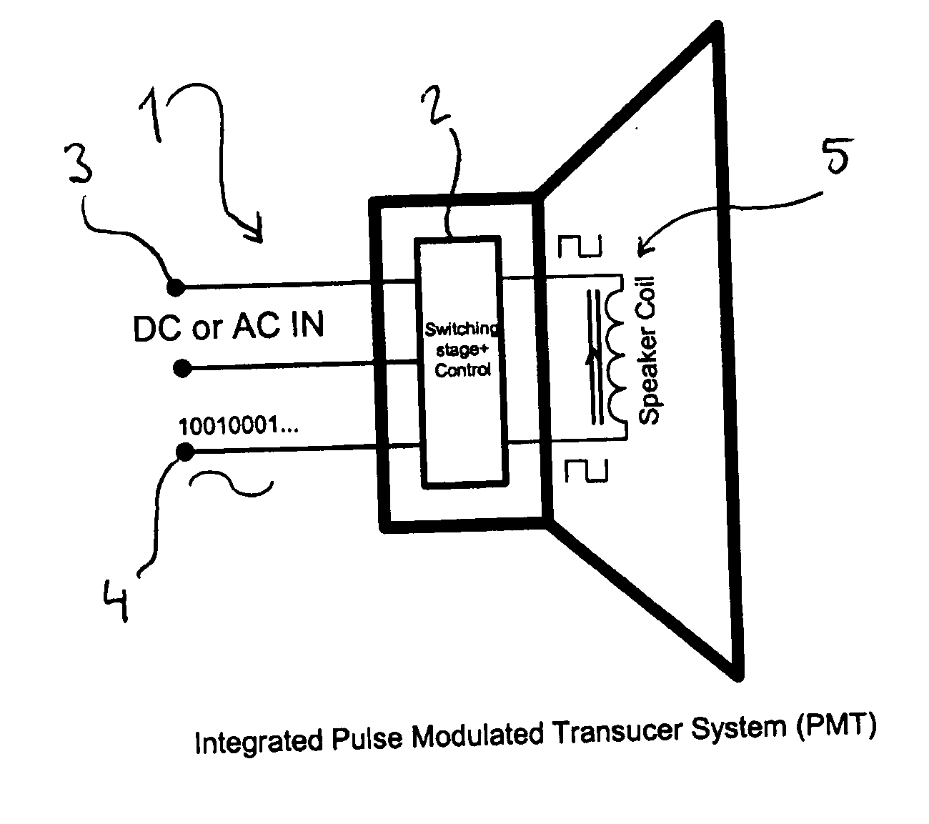
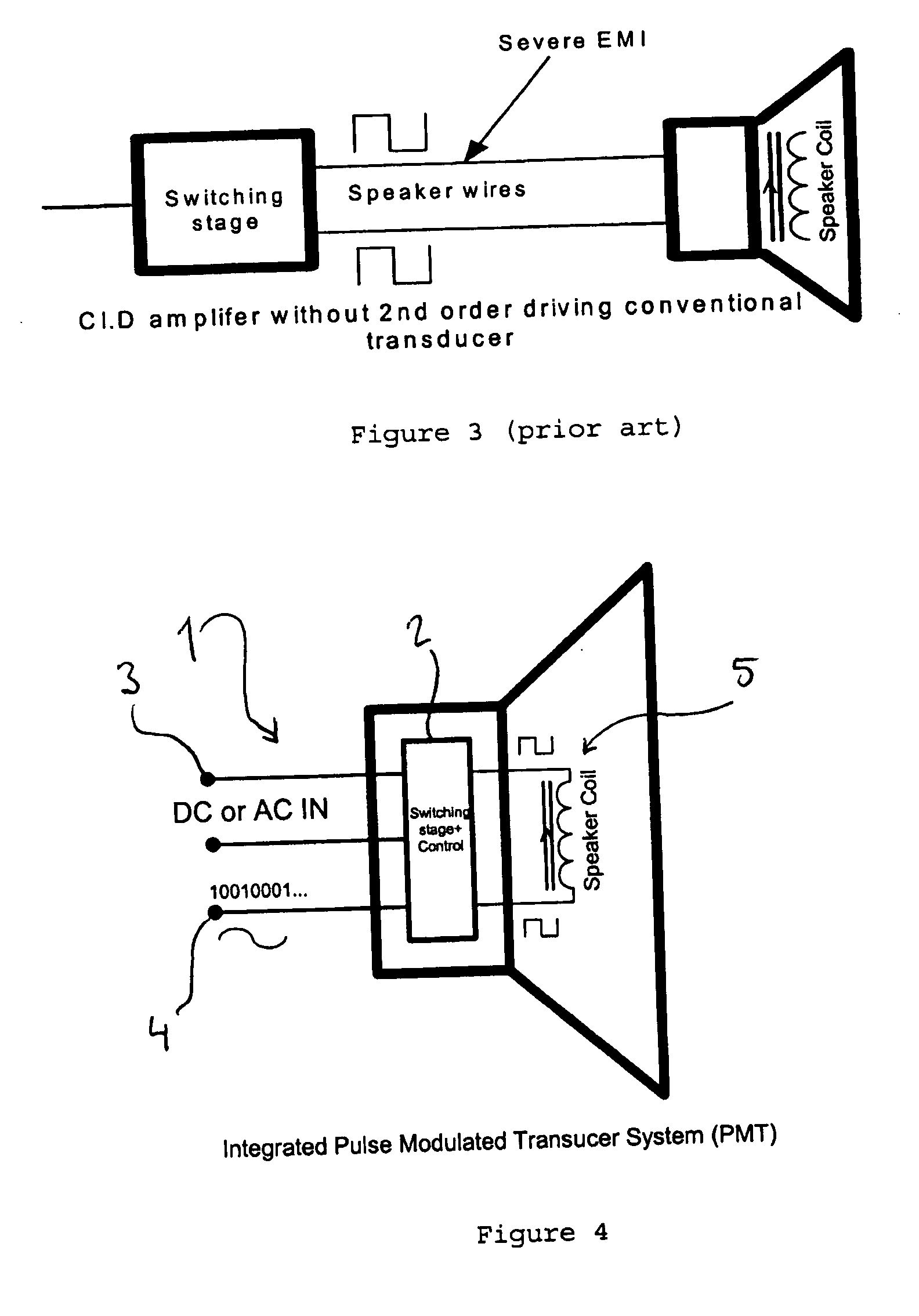
[0046] A schematic view of a Pulse Modulated Transducer 1 according to an embodiment of the invention is illustrated in FIG. 4. The power conversion can be implemented in a single conversion stage 2, switching directly from the rectified mains 3.

[0047] General to all preferred embodiments is that the modulator may be analog or digital and of PWM or PDM type in general. A "Controlled Oscillation modulator" can referably produce the pulse waveform as described in the applicant's patent number U.S. Pat. No. 6,362,702 or a synchronized Controlled Oscillation Modulator preferably producing a 3-level (Class BD type) PWM pulse waveform or a digital PWM modulator in general producing such a signal. This implementation will lead to lower losses in the voice-coil and magnetic structure of the electro-dynamic transducer. The modulating signal will be based on the source input 4 (analog or digital) and possibly also processed feedback information. Many feedback principles are viable in the PMT ...


PUM


Abstract

The present invention relates to an apparatus for converting an audio signal from a source (25) into audio waves, comprising a modulator (17), for modulating said audio signal, an amplifying switching stage (15), for amplifying a modulated audio signal supplied from the modulator, and a transducer (19). The transducer is connected directly to the switching stage, and is arranged to convert a pulse train from the switching stage into audio waves. Further, the modulator, the switching stage and the conversion means are integrated mechanically and electrically in one operational unit, being connectable directly to a mains power supply (12). By this electrical integration, no separate filtering is required, but instead the inherent qualities of the transducer are used for accomplishing filtering of the pulse train.

Description

[0001] The present invention relates to an apparatus for electric to acoustic conversion, comprising a modulator, an amplifying switching stage and electric-acoustic conversion means. The invention may advantageously be used for improved power conversion in audio reproduction.TECHNICAL BACKGROUND[0002] Conventional audio power conversion systems are based on three basic elements, a power supply generating DC voltage, an amplifier being fed by the power supply, and a speaker or transducer being fed with an amplified audio signal from the amplifier. Such a prior art system is illustrated in FIG. 1. In prior art, both linear and high efficiency switched power amplifiers and power supply solutions are known.[0003] In general, the elements in the audio amplification chain are considered as three distinctly different elements and designed as such. The elements are typically connected by cables and connectors to implement the complete system converting energy from mains to the acoustic out...

Claims


Application Information

Patent Timeline
IPC IPC(8): H03F3/217H04R3/00
CPCH04R3/00H03F3/2173
Inventor NIELSEN, KARSTEN
Owner BANG & OLUFSEN ICEPOWER
Why Eureka
Try Eureka