Methods and apparatuses for stretching polymers

a polymer and polymer technology, applied in the field of polymer characterization, can solve the problems of difficult to adapt the technique to a high-throughput operation, difficulty in further modification of the polymer, and difficulty in automating the technique, so as to reduce the channel depth

Inactive Publication Date: 2004-08-26
PATHOGENETIX
View PDF98 Cites 74 Cited by
  • Summary
  • Abstract
  • Description
  • Claims
  • Application Information

AI Technical Summary

Problems solved by technology

A challenge to the characterization of the linear sequence of monomers in a polymer chain has come from the natural tendency of polymers in most media to adopt unpredictable, coiled conformations.
Another attempt was made to stretch DNA by "gently" smearing it using a pipettor, a technique that is difficult to automate (PCT Publication No.
Nevertheless, this technique cannot be easily adapted to a high-throughput operation, since the immobilization is a rate-limiting step and further modification of the polymer is more difficult after the immobilization.
However, the laser can only hold one molecule in place at a time and has to be realigned for each subsequent molecule, making it unattractive for high-throughput analyses.
No attempt was made to characterize the quality of the stretching using this technique.
Furthermore, this technique shares the disadvantages of the previously-mentioned techniques (with respect to post-immobilization processing).
However, no data were given to determine the quality of the stretching of large polymers, and the technique is limited to analyzing approximately 3 megabases at a time.
It has also been found that this technique will not stretch single-stranded DNA due to differences in solvent interactions from double stranded DNA (Washizu et al.
One disadvantage to this technique is that, due to the presence of induced dipoles along the length of the DNA, samples agglomerate readily, and in a heterogeneous sample, it is difficult to accurately identify the components.
In addition, these experiments must be performed in deionized water in order to avoid the unwanted effects of Joule heating and electro-osmotic flow, presenting a sample preparation difficulty since most DNA exists in salt solutions or other solvents.
The DNA was then immobilized on the slide, making processing, e.g., fluorescent labeling, prior to stretching relatively difficult.
This method is relatively inflexible.
The use of a gel in this method necessitates a higher voltage than in solution to move DNA, and the end labeling precludes most other characterization of the DNA.
In addition, long DNA molecules tend to become entangled in a gel.
However, this technique takes a substantially longer time to run because of the field variation and shares the other disadvantages of electrophoresis.
This method is effective in creating restriction maps, however, predictable stretching in an agarose medium is difficult and the adaptation of the technique to high-throughput methods of analyzing uncut DNA is problematic.
Although many techniques have been developed that stretch biopolymers, and particularly DNA, they all have drawbacks, such as uniformity and reproducibility of stretching, ease of handling the biopolymer, and applicability to all types and sizes of biopolymers.
Furthermore, none of them are applicable to rapid analysis of information, such as is necessary to sequence large pieces of DNA on a reasonable time scale.

Method used


Image

  • Methods and apparatuses for stretching polymers
  • Methods and apparatuses for stretching polymers
  • Methods and apparatuses for stretching polymers

Examples


example 1

6.1 Example 1

Fabrication of a Chip for Stretching DNA and its Use in an Apparatus for Detecting Fluorescence Emission from Labeled DNA

[0227] Experimental Apparatus.

[0228] A sensitive optical apparatus for detection is shown in FIG. 24. The apparatus utilizes confocal fluorescence illumination and detection. Confocal illumination allows a small optical volume (of the order of femtoliters) to be illuminated. Both Rayleigh and Raman scattering are minimized using a small probe volume. The beam from a 1 mW argon ion laser is passed through a laser line filter (514 nm), directed to a dichroic mirror, through a 100.times.1.2 NA oil immersion objective, and to the sample. The fluorescent tag on the DNA can be one of several dyes including Cy-3, tetramethylrhodamine, rhodamine 6G, and Alexa 546. In addition, intercalator dyes can be used such as TOTO-3 (Molecular Probes). The fluorescence emission from the sample is passed through a dichroic, a narrow bandpass (e.g.. Omega Optical), focused...

example 2

6.2 Example 2

Stretching of Phage Lambda DNA Using Apparatuses of the Invention

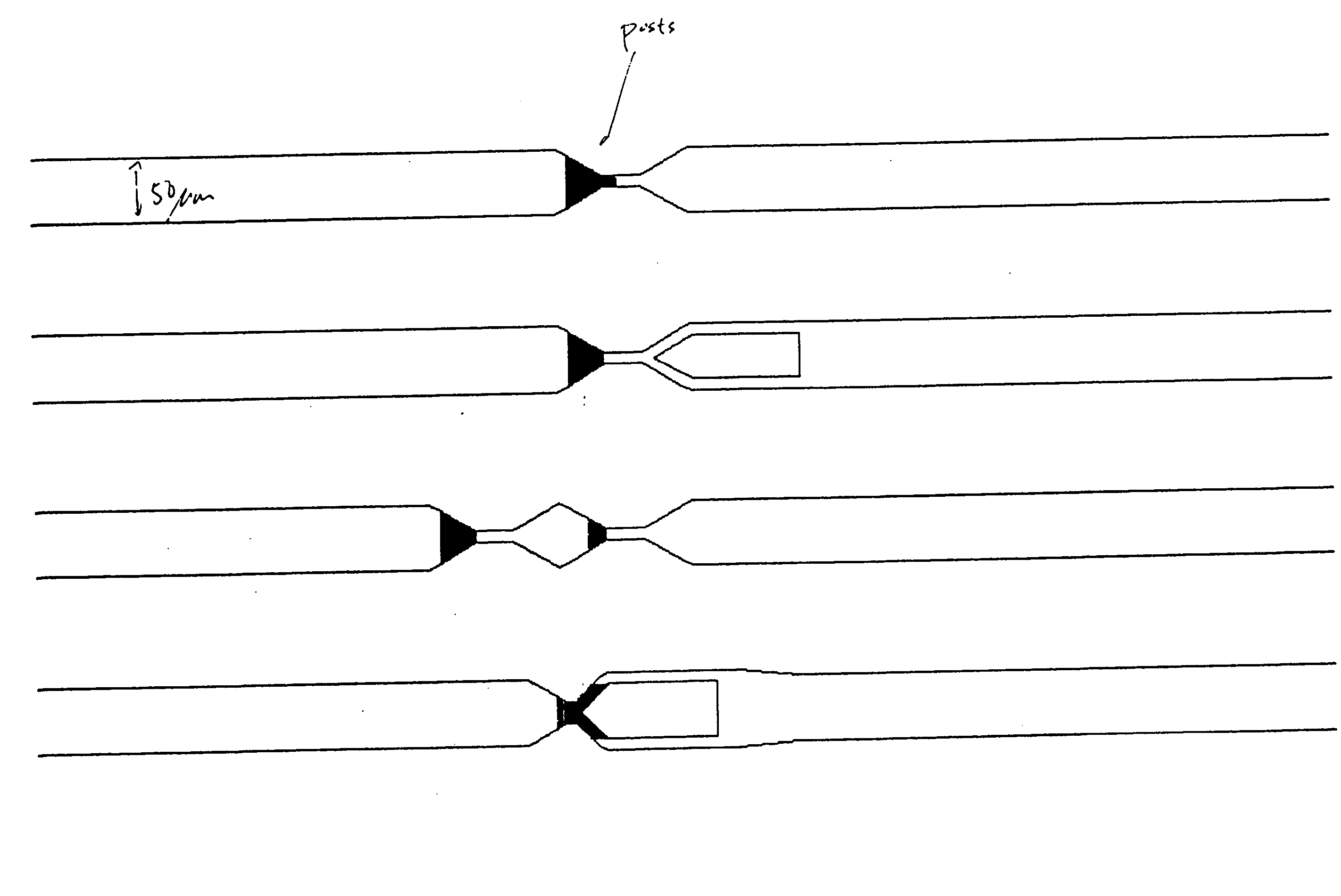
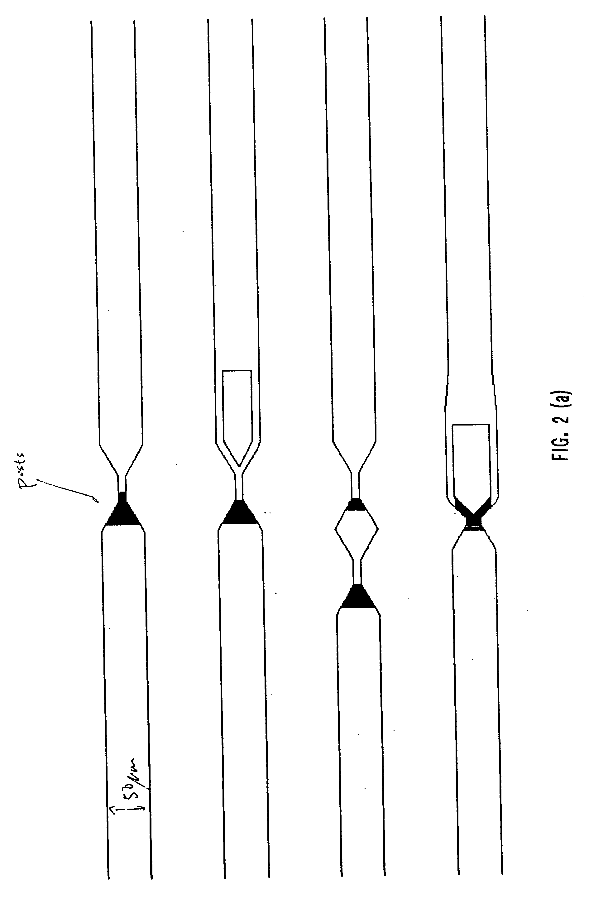
[0240] Two different apparatuses were used to obtain the data shown in FIGS. 30(a) and 30 (b). The apparatus shown in FIG. 20 was used to obtain the data shown in FIG. 30 (b). The apparatus used to obtain the data in FIG. 30 (a) had the same channel boundaries as the apparatus used to obtain the data shown in FIG. 30 (b) (i.e., the ratio of the sizes of the two tapered regions of the two-funnel apparatus were identical), except that there were no posts present in the structure.

[0241] A fused silica wafer (Hoya Corp., San Jose, Calif.) was etched with the pattern in FIG. 20 by a contractor using photolithographic methods described above. The wafer was diced into 1 cm by 2 cm chips using a dicing saw (e.g. from Disco Corp., Santa Clara, Calif.), and a fused silica cover slip (e.g. from Esco, Oak Ridge, N.J.) was attached by thermal bonding.

[0242] Double stranded lambda DNA (Promega, Madison, Wis.) having a u...


PUM

PropertyMeasurementUnit
angleaaaaaaaaaa
widthaaaaaaaaaa
widthaaaaaaaaaa

Abstract

The present invention provides structures and methods that allow polymers of any length, including nucleic acids containing entire genomes, to be stretched into a long, linear conformation for further analysis. The present invention also provides structures and methods for selecting and stretching polymers based on their lengths. Polymers are loaded into a device and run through the structures. Stretching is achieved by, e.g., applying shear forces as the polymer passes through the structures, placing obstacles in the path of the polymer, or a combination thereof. Since multiple molecules may be stretched in succession, extremely high throughput screening, e.g., screening of more than one molecule per second, is achieved.

Description

[0001] This application claims the benefit of U.S. Provisional Application No. 60 / 149,020, filed Aug. 13, 1999, which is incorporated herein by reference in its entirety.1. FIELD OF THE INVENTION[0002] The present invention relates to the general field of polymer characterization. More particularly, the invention relates to the use of structures to stretch a polymer or to select a polymer on the basis of length in a chip.2. BACKGROUND OF THE INVENTION[0003] Macromolecules are involved in diverse and essential functions in living systems. The ability to decipher the functions, dynamics, and interactions of macromolecules is dependent upon an understanding of their chemical and three-dimensional structures. These three aspects--chemical and three-dimensional structures and dynamics--are interrelated. For example, the chemical composition of a protein, and more particularly the linear arrangement of amino acids, explicitly determines the three-dimensional structure into which the polyp...

Claims


Application Information

Patent Timeline
Patent Type & Authority Applications(United States)
IPC IPC(8): B01F5/06B01F13/00B01L3/00C12Q1/68G01N1/28G01N15/14G01N33/44
CPCB01F5/061Y10T436/143333B01F5/0646B01F13/0059B01L3/50273B01L3/502746B01L3/502761B01L2200/0647B01L2200/0663B01L2300/0816B01L2400/086C12Q1/6869G01N1/286G01N15/1456G01N15/1459G01N33/442G01N2015/1493G01N2015/1495B01F5/064B01L2300/0883B01F25/431B01F25/432B01F25/433B01F33/30
Inventor CHAN, EUGENE Y.GLEICH, LANCE C.WELLMAN, PARRIS S.
Owner PATHOGENETIX
Why Eureka
Try Eureka