Method for adjusting an internal combustion engine with exhaust gas recirculation and device for carrying out said method

Inactive Publication Date: 2004-11-25
MENAG HLDG
View PDF8 Cites 10 Cited by
  • Summary
  • Abstract
  • Description
  • Claims
  • Application Information

AI Technical Summary

Benefits of technology

0009] The present invention is underlain by the task of creating a novel method of adjusting a fixed internal combustion engine, especially a gas engine, that will not be associated with the aforesaid difficulties and, in particular, will be free of the drawbacks of the known methods and make it

Problems solved by technology

Such a Lambda-1 internal combustion engine is however associated with the drawback of having a relatively small efficiency and therefore a small power yield.
Although the power yield can be increased by means of supercharging and precompression of the air-fuel mixture, this measure steps up the pressure and temperature in the combustion chamber and thus facilitates the self-ignition of unburnt components of the fuel, so-called knocking, and considerably reduces the useful life of the engine.
A Lambda-1 internal combustion engine with supercharger cannot therefore be used for a fixed installation that is to have a long useful life.
When these gases are used as fuel gas, they cannot be used in combination with a three-way catalytic converter, because it

Method used


Image

  • Method for adjusting an internal combustion engine with exhaust gas recirculation and device for carrying out said method
  • Method for adjusting an internal combustion engine with exhaust gas recirculation and device for carrying out said method

Examples


Example

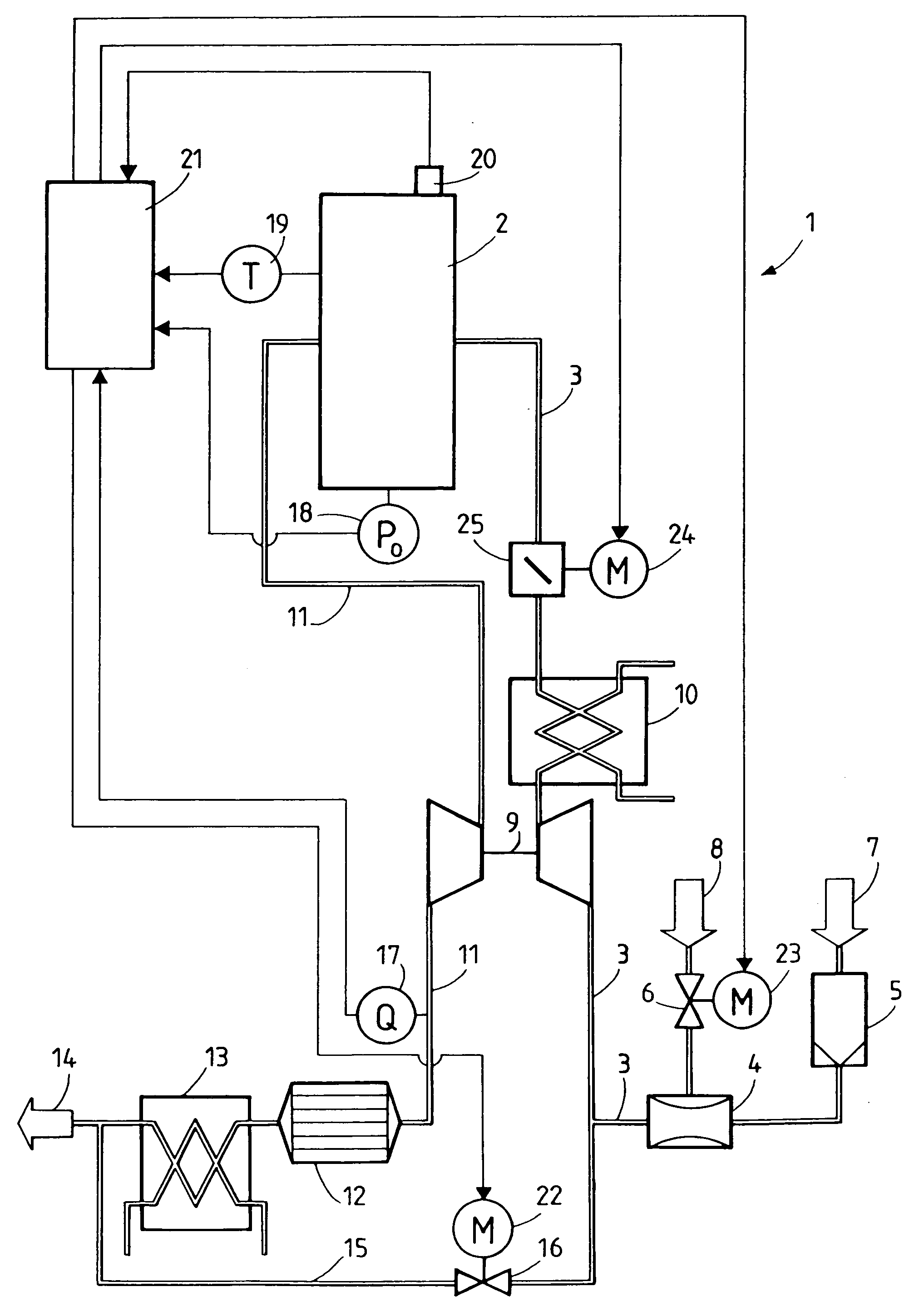
[0016] The device, which in FIG. 1 is generically indicated by the reference number 1, comprises a gas engine 2 mounted in a frame not shown in the FIGURE. A fuel induction line 3 leads the air-fuel mixture into the gas engine 2. Associated with this fuel induction line 3 on its input side is a gas mixer 4 into which fuel 8 can be introduced through a shutoff device or valve 6 that can be opened as and when required, while air 7 can be admitted through the filter 5.

[0017] In the fuel induction line 3 there is also provided a turbosupercharger 9, which increases the gas throughput of the engine 2 by compressing the gas mixture that is to be burnt and thus makes possible a greater power density. The turbosupercharger 9 is also provided with a cooler 10 for cooling the compressed air-fuel mixture.

[0018] An exhaust gas line 11 leads from the gas engine 2 to the three-way catalytic converter 12 with its associated exhaust gas cooler 13. Both are of known construction and are provided wit...


PUM


Abstract

The invention relates to a method for adjusting a device (1) which essentially consists of a Lambda-1 internal combustion engine (2), a fuel induction line (3), a supplemental unit (9) arranged in the induction line (3) for compressing an air-fuel mixture required for combustion, a catalytic converter (12) arranged in the exhaust gas flow, and an exhaust gas recirculation line (15) which is disposed downstream from the catalytic converter (12), leading into the fuel induction line (3) and which is used to supply cooled exhaust gas to the air-fuel mixture. The inventive method is especially characterized in that the amount of exhaust gas which is to be supplied to the air-fuel mixture per time unit is adjusted according to the combustion chamber temperature measured in the combustion chamber of the internal combustion engine (2) in conjunction with the lambda adjustment. Preferably, said combustion chamber temperature and the amount of exhaust gas to be supplied to the air-fuel mixture per unit of time are measured and adjusted continuously. Especially when the so-called problem gases are used, the useful life of this probe becomes substantially shortened and this, in its turn, leads to high maintenance costs.

Description

TECHNICAL AREA[0001] The invention relates to a method for adjusting an internal combustion engine with exhaust gas re-circulation and a device for carrying of the method, namely a method in accordance with the preamble of claim 1 and a device in accordance with claim 4.[0002] The device is intended, for instance, for a unit-type heating station with a fixed gas engine.[0003] Successful and economic operation of unit-type heating stations depends essentially on three criteria. The power density, the efficiency and taking due account of the limiting emission values.[0004] The specific emission rates of the combustion products--and among these especially the emission of NO.sub.4-- assume a central position among the aforementioned three criteria. This is due to government regulations, which specify maximum NO.sub.x values of the order of 50 to 80 ng / Nm.sup.3 for all units that are operated with fossil fuels. A gas engine, which satisfies this condition with a typical emission of 30 mg...

Claims


Application Information

Patent Timeline
IPC IPC(8): F01N3/24F02D19/02F02D21/08F02D35/02F02D41/00F02D43/00F02M26/15
CPCF02B29/0406F02D35/025F02D41/0027F02D41/005F02D41/1454F02M25/0709F02M25/0718Y02T10/47F02D19/023Y02T10/22F02M26/06F02M26/15Y02T10/12Y02T10/40F02D35/02
Inventor REIDER, OTMARLAGIER, GEORGES
Owner MENAG HLDG
Why Eureka
Try Eureka