
Interconnection structure and fabrication method thereof

Active Publication Date: 2005-01-06
MARLIN SEMICON LTD
View PDF10 Cites 7 Cited by
  • Summary
  • Abstract
  • Description
  • Claims
  • Application Information

AI Technical Summary

Benefits of technology

[0011] The invention provides an interconnection structure having a reduced stress and a fabrication method thereof, so as to prevent damaging a via or conductive line that lead to an increase in resistance or leakage current.
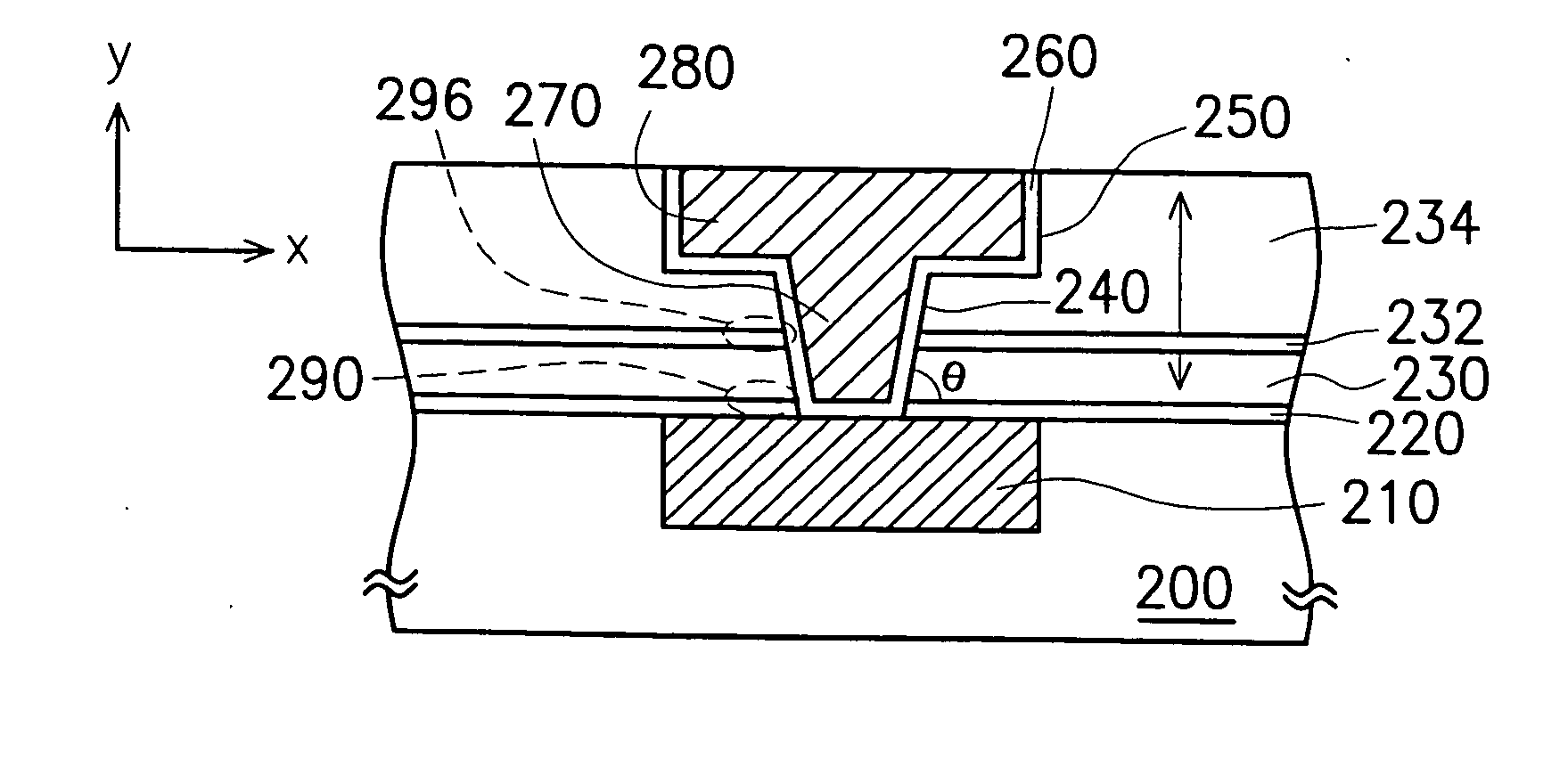
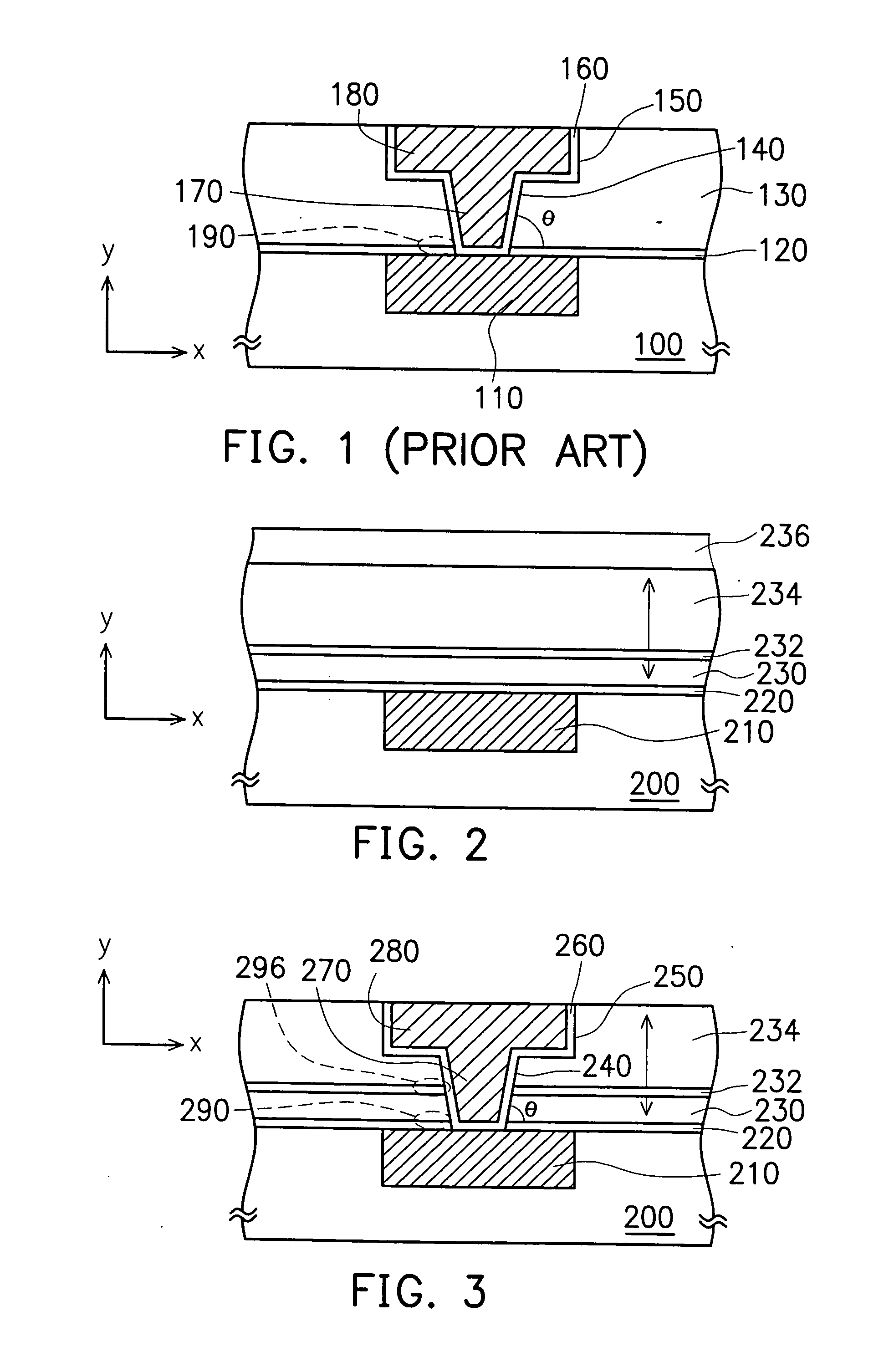
[0015] According to the invention described above, the stress redistribution layer having a characteristic similar to the substrate is sandwiched between the organic low-k material layers. Hence, the two organic low-k material layers can be made thinner than the conventional organic low-k material layer. The stress redistribution layer can scatter the stress produced from the organic low-k material layers, so that the stress that accumulate at a junction underneath the organic low-k material layers is reduced and redistributed to elsewhere. Therefore, the interconnection structure as described in the invention would not cause a rise in resistance of the via, as well as a damage of the via. In addition, delamination would not occur easily at a junction between a diffusion barrier layer and a copper layer, thus minimizing chances of short-circuiting between conductive lines of different metallization levels.

Problems solved by technology

This would reduce the operation speed of the device due to the well-known RC delay.
On the other hand, after inspecting a batch of the failed devices, it is found that there are many damaged via as well as occurrence of delamination at a junction between the diffusion barrier layer 160-copper layer 110 caused by an oversized stress Syy.
The damaged via would make the device ineffective, while the delamination that occurs between the diffusion barrier layer 160-copper layer 110 would cause a high leakage current.
Thus, to prevent other problems caused by an oversized stress Sxx, the room for adjusting the stress Syy becomes limited.

Method used


Image

  • Interconnection structure and fabrication method thereof
  • Interconnection structure and fabrication method thereof

Examples


Embodiment Construction

[0019]FIGS. 2-3 are schematic diagrams illustrating the method of fabricating the dual damascene interconnection structure according to one preferred embodiment of the present invention, wherein FIG. 3 also illustrates the dual damascene interconnection structure according to one preferred embodiment of the present invention.

[0020] Referring to FIG. 2, a substrate 200 is provided, wherein the substrate 200 has a metal layer 210, such as a copper layer already formed therein. Also, a cap layer 220 made of material, such as silicon nitride is already formed over the substrate 200. Next, an organic low dielectric constant (low-k) material layer 230 is formed over the substrate. The organic low-k material layer 230 may be made of a material such as polyimide, fluorinated polyimide, poly(arylene ether), parylene, polytetrafluoroethylene (PTFE), and benzocyclobutene (BCB).

[0021] Still referring to FIG. 2, a stress redistribution layer 232 is formed on the organic low-k material layer 23...


PUM


Abstract

An interconnection structure and a fabrication method thereof. A first organic low-k material layer, a stress redistribution layer, a second organic low-k dielectric layer are formed in sequence over a substrate, followed by forming an opening in the first organic low-k material layer, the stress redistribution layer, and the second organic low-k dielectric layer. The opening is then filled with a conductive material to form an interconnection structure. The stress redistribution layer has a heat expansion coefficient closer to that of the substrate, while such heat expansion coefficient differs more significantly from those of the first and second organic low-k material layers.

Description

BACKGROUND OF THE INVENTION [0001] 1. Field of the Invention [0002] The invention relates to a semiconductor device and a fabrication method thereof. More particularly, the invention relates to an interconnection structure and a fabrication method thereof, which are characterized by an ability to reduce stress. [0003] 2. Description of the Related Art [0004] As the line width of the semiconductor device keeps reducing to achieve a higher integration, the resistance of the interconnection in the device becomes higher, and a parasitic capacitance that occurs between the conductive lines also becomes more significant. This would reduce the operation speed of the device due to the well-known RC delay. So, Copper (Cu) with a low resistance, as well as low dielectric constant (low-k) materials having a dielectric constant lower than that of silicon oxide become necessary choices of materials in the manufacture process. And among different low-k materials, organic low-k material is one typ...

Claims


Application Information

Patent Timeline
IPC IPC(8): H01L21/44H01L21/4763H01L21/768
CPCH01L21/76801H01L21/76829H01L21/76807
Inventor HSIUNG, CHIUNG-SHENGYANG, CHIH-CHAOYANG, GWO-SHILYEH, MING-SHIHCHEN, JEN-KON
Owner MARLIN SEMICON LTD
Learn More