

Method for thermal analysis and system for thermal analysis
a technology of thermal analysis and system, applied in the direction of material heat development, optical radiation measurement, instruments, etc., can solve the problems of not having a two-dimensional thermal analysis method, difficult for these methods to thermally analyze minute portions, etc., and achieve the effect of easy follow-up or trace, and faster measurement speed
- Summary
- Abstract
- Description
- Claims
- Application Information
AI Technical Summary
Benefits of technology
Problems solved by technology
Method used
Image

Examples
example 1
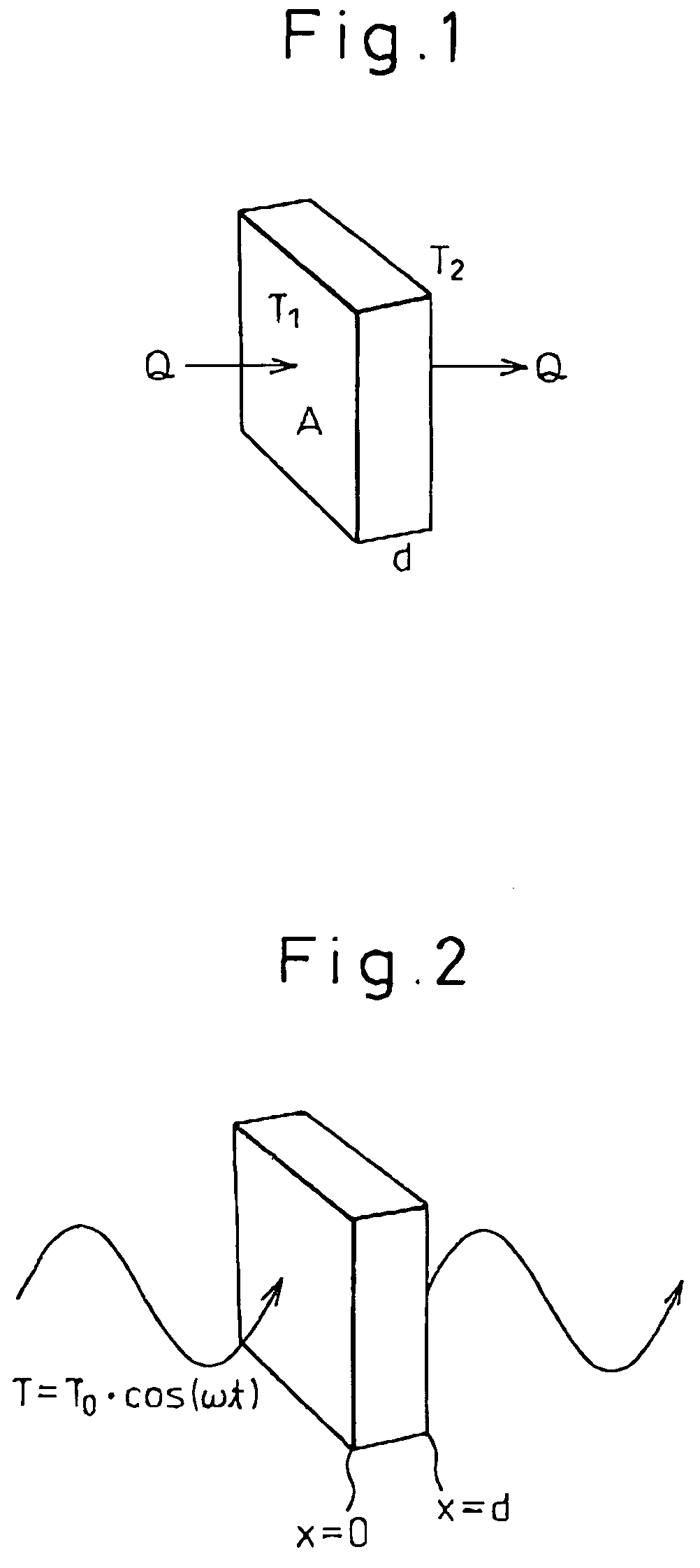
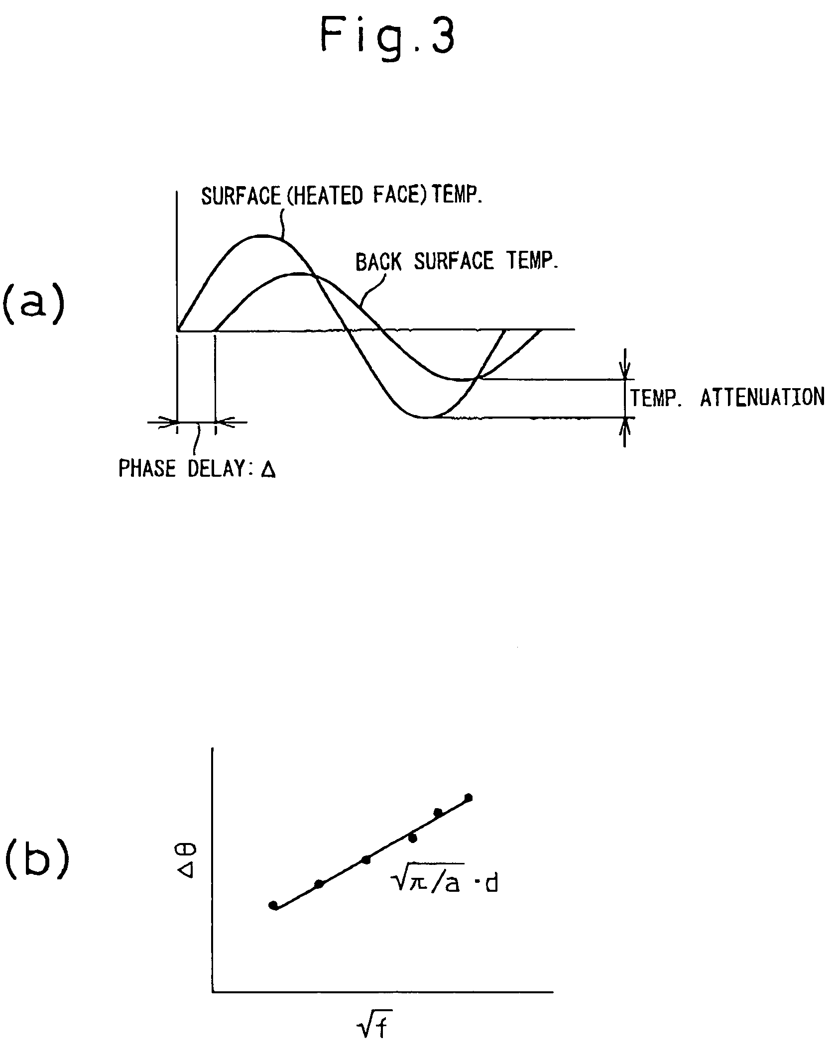
(Example of Determining the Coefficient of Thermal Diffusion in the Direction of Thickness of a Film from Measurement of Phase Delay when a Temperature Wave is Diffused in the Direction of Thickness of a Film)
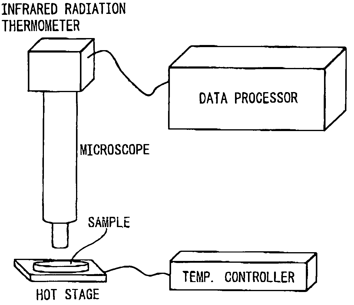
Experimental Method: A ribbon-shaped, flat heater electrode (1 mm×5 mm, thickness: 50 nm, resistance of flat electrode: 50 ohms) was formed by sputtering on Pyrex glass (thickness: 0.5 mm, mfd. by Corning Inc., trade name: Pyrex 7740) measuring about 2 cm×3 cm. The metal sputtering conditions used at this time were as indicated below.
<Metal Sputtering Conditions>
Sanyu Electronics, 5 mA, 2 kV, 5 minutes
A temperature wave was generated by applying an alternating current having a frequency of 0.5 Hz to the flat heater electrode obtained in the manner described above. The alternating current voltage input at this time was 3 Vp-p, the resistance of the flat electrode was 48 ohms, and the waveform was a sine wave.
Sample: A commercially available food wrapping film (poly...
example 2
(Analysis of Cooling Process of Plant Endothelial Cells-Analysis of Intercellular and Intracellular Crystallization Rate and Analysis of Temperature Propagation)
Experimental Method: The cooling process of onion endothelial cells adhered to a slide glass was measured on a sample stage provided with a Peltier element on a cooling plate placed on ice by using an infrared camera similar to that used in Example 1. During the cooling process, the cells were cooled at a cooling rate of about 200° C. / min over the range from room temperature to the vicinity of −30° C. The shutter speed of the infrared camera was set to 2 ms, the number of frames was set to 200 frames / second and the number of pixels was set to 128×128 pixels.
Sample: The first or second layer of the bud and the exodermis at a location nearly in the center from the location of the root were sampled from the outside of a fresh onion and adhered to a slide glass for use as the sample. The thickness of the exodermis was about...
example 3
(Temperature Calibration Method by Using a Black Body)
Experimental Method: A Teflon sheet measuring 1 cm×1 cm (thickness: 20 μm) was used for the measurement sample. A portion of the sample in the form of flat plate (size: 1 cm×1 cm) was coated with a carbon spray (emissivity: 0.94, thickness: 1 μm) to prepare a pseudo black body. A calibrated chromel-alumel thermocouple having a diameter of 25 μm (trade name: SPAL-001-50, SPCH-001-50, Omega Engineering Inc.) was attached to the surface of this pseudo black body, and the temperature was loaded into a personal computer (trade name: Inspiron 3000, Dell) through a predetermined interface (trade name: AT-GPIB, National Instruments) from the thermocouple. The conditions for capturing of the temperature data at this time were as shown below.
<Temperature Data Capturing Conditions>1000 Points / Sec
A ceramic heater measuring 1 cm×1 cm (trade name: Sakaguchi E. H. VOC) was adhered to the bottom (lower side) of the sample by using sil...
PUM
 Abstract
Description
Claims
Application Information